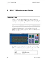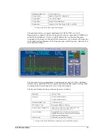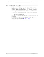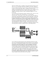
Both the rear panel BNC monitor output and speaker jack output can select signals from
either before or after the programmable filter bank, or from recorded AC coupled signals
stored in the AI-5120's internal memory. The gain of each output is adjustable over a
wide range.
4.2 Indicators & Connections
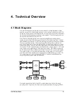
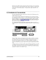
The AI-5120 front panel is quite simple and only contains four LED indicators and two
telephone interface RJ-11 jack.
The two left side indicators "Ready" and "Communication" show the status of the unit
and communication activity respectively. Under normal operation the "Ready" indicator
should be illuminated. If it is flashing an internal fault is detected. When the "Ready"
indicator is flashing, the state of the "Ringing" and "Off-Hook" indicators determine the
specific fault condition. See Appendix B: Error Codes for information describing the
fault conditions and possible solutions.
The communication indicator briefly flashes anytime data is either sent to the PC or
received from the PC. Data transferred on either the USB or RS-232 causes the indicator
to flash.
Communication
Ready
Off-Hook
Ringing
Line
Bypass
Unit Ready
Communication with Host
Ringing Detected
Terminal Equipment Off-Hook
RJ-11 Connectors
Tip/Ring Interface
300 V
Peak
CAT
I
When the "Ready" indicator is illuminated (no fault condition), then the two right side
LED's show when the AI-5120 has detected ringing or when the line state is in the off-
hook condition. Ringing is detected if an AC voltage exceeding 40 Vrms with a
frequency in the range of 10 to 100 Hz. is measured. The AI-5120 considers the line
state to be off-hook if the measured voltage is below a specified threshold (by default 19
volts)
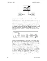
A telephone line can be connected to either of the AI-5120 front panel RJ-11 jack, as they
are configured in parallel to each other. Typically, the telephone line from the central
office, PBX, or line simulator is connected to one of the RJ-11 jacks, while the terminal
equipment is connected to the other RJ-11 jack.
AI-5120 User Guide
15

