


UNO-410 User Manual
14
2.3
Internal I/O Connectors and Switches
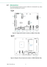
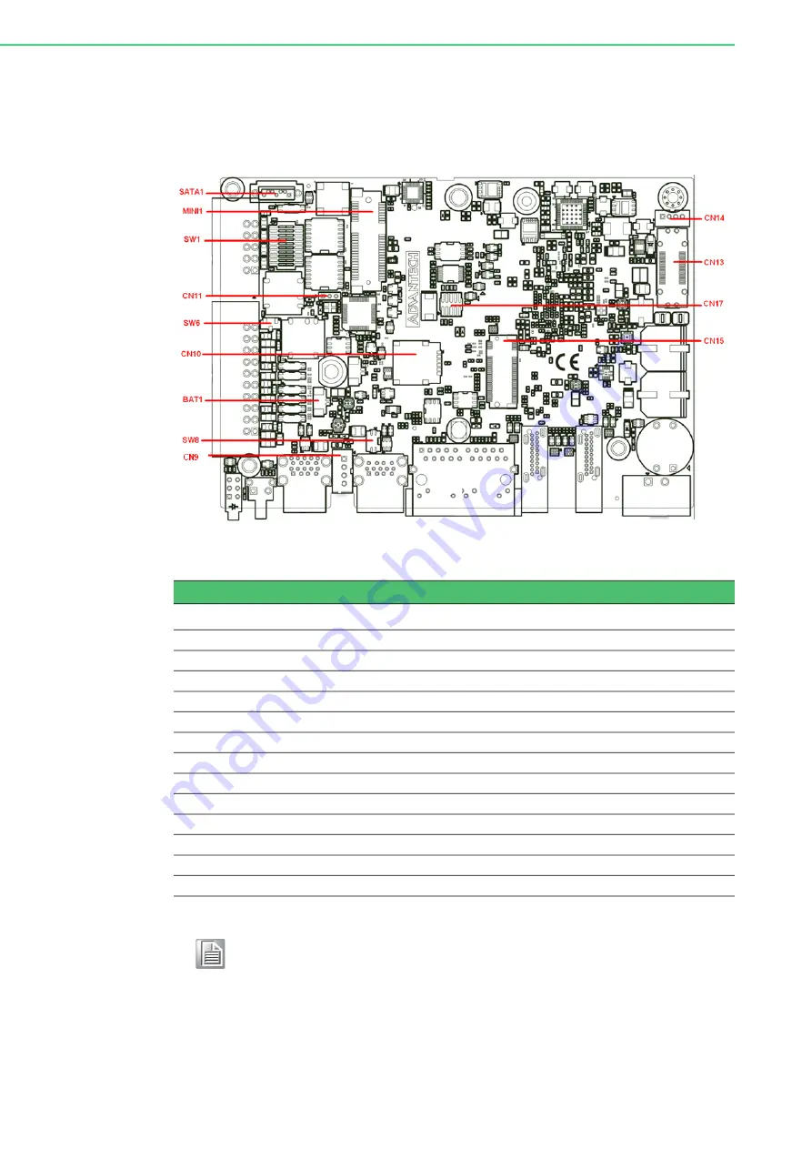
The following figure shows the locations of internal connectors and switches on the
UNO-410’s motherboard.
Figure 2.8 Locations Internal I/O Connectors/Switches for UNO-410
Table 2.3: Internal Connectors and Jumper Switches
Label
Function
MINI1
MiniPCIe connector
CN15
M.2 B key for 2242/3042/3052 connector
CN10
Nano SIM slot connector
CN14*
iDoor Power connector
SATA1
SATA Signal connector
CN9
SATA Power connector
CN13
Reserve for connector expansion
CN17
Debug connector
CN11
Clear CMOS connector
SW1
COM Port RS232/422/485 settings
SW6
DI Setting (Dry/Wet)
SW8
AT/ATX/Remote setting
BAT1
RTC Battery connector
Note!
*This power is from DC Power inputs.
Summary of Contents for UNO-410
Page 1: ...User Manual UNO 410 Explosion Proof DIN Rail Gateway...
Page 10: ...UNO 410 User Manual x...
Page 18: ...UNO 410 User Manual 6...
Page 30: ...UNO 410 User Manual 18...
Page 50: ...UNO 410 User Manual 38...
Page 51: ...Appendix A A System Settings Pin Assignments...
Page 65: ...53 UNO 410 User Manual Appendix A System Settings Pin Assignments...