


13
Chapter 2
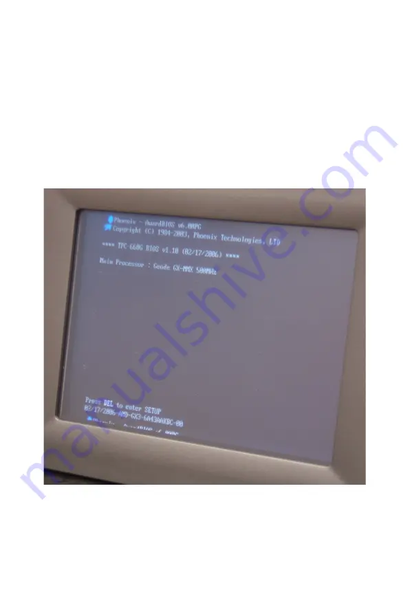
Figure 2.7: Bootup Screen
6.
Calibrate the touchscreen. The detailed procedure is described in
the appendix.
Note:
When turning on the system, the bootup screen
before entering any operating system is shift to
the right side as the photo below. This is due to
the BIOS limitation and appears if the application
is running in console mode. The display is nor-
mal after entering Windows XP, Windows XP
embedded and Windows CE system.
Summary of Contents for TPC-660G
Page 1: ...TPC 660G AMD LX800 Touch Panel Computer with 6 4 VGA TFT LCD User Manual ...
Page 10: ...TPC 660G User Manual x ...
Page 18: ...TPC 660G User Manual 8 ...
Page 19: ...2 CHAPTER 2 System Setup This chapter provides a brief explana tion for operating TPC 660G ...
Page 24: ...TPC 660G User Manual 14 ...
Page 25: ...2 CHAPTER 3 System Engine ...
Page 27: ...17 Chapter3 Figure 3 1 Main Board Connectors 1 Figure 3 2 Main Board Connectors 2 ...
Page 28: ...TPC 660G User Manual 18 ...
Page 32: ...TPC 660G User Manual 22 Figure 4 4 Update Wizard 2 Figure 4 5 Update Wizard 3 ...
Page 33: ...23 Chapter4 Figure 4 6 Update Wizard 4 Figure 4 7 Update Wizard 5 ...
Page 36: ...TPC 660G User Manual 26 Figure 4 12 Install Wizard 2 Figure 4 13 Install Wizard 3 ...
Page 38: ...TPC 660G User Manual 28 ...
Page 39: ...2 CHAPTER 5 Features in Windows XP Embedded Sections include EWF HORM Advantech Utilities ...
Page 43: ...2 APPENDIX A Serial Port Settings ...
Page 47: ...2 APPENDIX B Watchdog Timer Programming ...
Page 57: ...2 APPENDIX C Watchdog Timer Programming on WinCE ...
Page 64: ...TPC 660G User Manual 54 ...
Page 71: ...61 AppendixE Figure E 3 Install Wizard 2 Figure E 4 Install Wizard 3 ...
Page 74: ...TPC 660G User Manual 64 Figure E 8 Standard Calibration 2 Figure E 9 Standard Calibration 3 ...
Page 76: ...TPC 660G User Manual 66 Figure E 11 Advanced Calibration 2 Figure E 12 Plot Calibration Data ...


