background image

5

TPC-5000 Series User Manual

Chapter 1

G

eneral

Information

1.6

Panel Mounting

1.

There is an adhesive waterproof gasket on the Mg front bezel. Ensure that the 
waterproof gasket is in place before installing the TPC system in the panel 
opening.

2.

Install the TPC in the panel opening.

3.

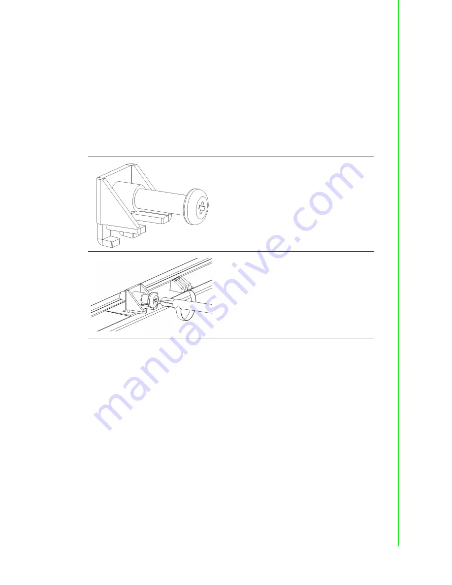
Retrieve the clamps and long screws from the accessory pack. Hook the clamps 
the holes located on the four sides of the bezel. Insert screws into every clamp 
and tighten them to fasten the clamp in place. These screws will push the 
mounting panel and secure the unit.

4.

The suggested mounting panel thickness is less than 6 mm (0.236 in).

Figure 1.2 Panel mounting

Insert the screws into each clamp and tighten 
them to fasten the clamp in place. 

Hook the clamps into the holes and fasten the 
screws
Torque: 2 kgf-cm
These screws will push the mounting panel and 
secure the unit.

Summary of Contents for TPC-5152T-633AE

Page 1: ...User Manual TPC 5212W TPC 5172T TPC 5152T TPC B500 Series 6th Generation Intel Core i Computer...

Page 2: ...ominated biphenyls PBB Polybrominated diphenyl ethers PBDE 1 0 1 wt 0 01 wt Note 1 Exceeding 0 1 wt and exceeding 0 01 wt indicate that the percentage content of the restricted substance exceeds the r...

Page 3: ...ominated biphenyls PBB Polybrominated diphenyl ethers PBDE 1 0 1 wt 0 01 wt Note 1 Exceeding 0 1 wt and exceeding 0 01 wt indicate that the percentage content of the restricted substance exceeds the r...

Page 4: ...ominated biphenyls PBB Polybrominated diphenyl ethers PBDE 1 0 1 wt 0 01 wt Note 1 Exceeding 0 1 wt and exceeding 0 01 wt indicate that the percentage content of the restricted substance exceeds the r...

Page 5: ...TPC 5212W 633AE TPC 5212W 673AE TPC 5212W 634AE TPC 5212W 674AE TPC5212W63A1701ET TPC5212W63A1702ET TPC5212W63A1703E T TPC5212W63A1704ET TPC5212W63A1705ET TPC5212W63A1801ET TPC5212W63A1802ET TPC5212W...

Page 6: ...TPC5152T63A1702E T TPC5152T63A1703E T TPC5152T63A1704E T TPC5152T63A1705E T TPC5152T63A1801E T TPC5152T63A1802E T TPC5152T63A1803E T TPC5152T63A1804E T TPC5152T63A1805E T TPC5152T63A1901E T TPC5152T6...

Page 7: ...eplacement materials service time and freight Please consult your dealer for more details If you believe your product is defective follow the steps outlined below 1 Collect all the information about t...

Page 8: ...energy and if not installed and used in accordance with the instruction manual may cause harmful interference to radio communications Opera tion of this equipment in a residential area is likely to c...

Page 9: ...electrical shock 13 Never open the equipment For safety reasons the equipment should be opened only by qualified service personnel 14 If one of the following occurs have the equipment checked by servi...

Page 10: ...TPC 5000 Series User Manual x 1 2 3 4 5 6 7 8 9 10 11 12 13 14 15 20 C 4 F 60 C 140 F 16 17 IEC 704 1 1982 70 18 19 IEC 704 1 20 21 30 10 22 2 2 1...

Page 11: ...1 Chipset Graphics ME and LAN Driver Installation 11 2 3 2 Watchdog Driver Installation 11 2 4 Panel Mounting 13 2 5 Cabinet Installation and Earth Grounding Setup 15 2 6 Power Digital Ground and Eart...

Page 12: ...Chapter 4 Easy Installation 27 4 1 Easy Installation 28 4 2 UI Operation 30 Table 4 1 Status Indicator Table 30 Table 4 2 Button Code Definition 34 4 3 COM1 RS 232 35 4 4 COM2 RS 422 485 35 4 5 RS 42...

Page 13: ...Chapter 1 1 General Information...

Page 14: ...are often unreliable and cause dust to circulate inside the equipment Bright Display The TFT LED LCD satisfies industrial demands for clear and precise interfaces and features a wide operating temper...

Page 15: ...0 140 170 160 178 178 Backlight Life 50 000 hr 50 000 hr 50 000 hr 30 000 hr 50 000 hr Contrast Ratio 700 1 700 1 800 1 1000 1 5000 1 Touch Type 5 wire resistive Projected capacitive Projected capacit...

Page 16: ...3 7 Amp 1 5 I O Port Arrangement The arrangement of the I O ports are as shown in Figure 1 1 Figure 1 1 I O port arrangement A Wi Fi antenna B NFC card reader C Logo D iKey E Home key F Power indicato...

Page 17: ...e accessory pack Hook the clamps the holes located on the four sides of the bezel Insert screws into every clamp and tighten them to fasten the clamp in place These screws will push the mounting panel...

Page 18: ...Panel Dimensions mm Cutout Size mm Wall Thickness mm Display Size X1 Y1 Z1 X2 Y2 Z Min Z Max 12 311 8 238 85 6 303 229 1 6 15 383 2 307 3 86 374 5 298 5 1 6 17 410 4 343 4 86 8 401 3 334 8 1 6 18 488...

Page 19: ...Chapter 2 2 System Setup...

Page 20: ...massive impact on the device Therefore please use the original packaging during transporta tion and storage If the TPC system is transported in cold weather or is exposed to extreme variations in tem...

Page 21: ...power lines The power lines can either be from a power adapter or an in house power source Figure 2 4 Power connector and power lines Warning We recommend turning the system power off before adding o...

Page 22: ...Manual 10 5 Plug the power lines into the system s power receptor Figure 2 5 Power receptor and button pin assignment 6 Connect the power to the system 7 Calibrate the touchscreen only applicable for...

Page 23: ...hat the computer meets the hardware and software requirements to run the Advantech watchdog driver 2 If you do not already have the installer for the Advantech watchdog driver download it from the Adv...

Page 24: ...nual 12 3 Click the Install button to continue the installation of the Advantech watchdog driver software 4 Click the Restart or Close button on the Advantech Watchdog Driver Setup Wizard pop up scree...

Page 25: ...13 TPC 5000 Series User Manual Chapter 2 System Setup 2 4 Panel Mounting 1 Position the TPC system against the panel 2 Insert clamps into the sides of the TPC unit...

Page 26: ...TPC 5000 Series User Manual 14 3 Secure the clamps to the panel using the screws provided in the accessory box...

Page 27: ...net the TPC system s ground the cabinet s ground and an earth ground should be connected together 1 Installing the TPC system in the cabinet Step A Connect the cabinet to an earth ground Step B Embed...

Page 28: ...D issues general USB devices are designed as a chas sis and digital short However the TPC system prevents damage to USB devices ESD and EMI solutions are designed to use the power ground as a vent pat...

Page 29: ...Remove the Rear Box 1 Remove the 2 screws on the extension door 2 Slide the rear cover off to remove it Figure 2 6 M 2 SSD installation 3 Remove the screws on the I O bracket of the rear box module to...

Page 30: ...he screws in the screw holes Figure 2 8 M 2 SSD installation layout 2 7 3 iDoor Installation The iDoor module should be affixed in place using two screws that are already set in the main board Insert...

Page 31: ...e box module through the track After insertion tighten the screws to affix the riser card in place Figure 2 10 Riser card installation 2 7 5 SIM Card Installation via Mini PCIe The SIM card should be...

Page 32: ...he front panel 1 Open the bracket at the back of the front panel 2 Insert the Wi Fi module into the mPCIe slot connect the antenna and tighten the affixing screws Figure 2 12 Wi Fi module installation...

Page 33: ...21 TPC 5000 Series User Manual Chapter 2 System Setup...

Page 34: ...TPC 5000 Series User Manual 22...

Page 35: ...Chapter 3 3 Features of Windows Embedded OS...

Page 36: ...he device to its original state Note that there is no disk based overlay support for Windows Embedded Standard 7 EWF works at the sector level on protected disks and allows users to implement changes...

Page 37: ...TPC 5000 Series User Manual Chapter 3 Features of Windows Embedded OS 2 Access the EWF tab and click on the Enable button 3 After the system is rebooted automatically EWF functionality will be enable...

Page 38: ...d folders Writes to folders with write through exceptions will persist when the device is restarted Advantech provides a utility to run FBWF Follow the steps outlined below to enable this function 1 A...

Page 39: ...Chapter 4 4 Easy Installation...

Page 40: ...a cabinet Step 1 Models with a 4 3 screen ratio 1 Use the snap hooks at the top of the TPC unit to hook the system in the cabinet 2 Release the pillars at the bottom of the TPC unit to install the sys...

Page 41: ...the snap hooks flip back The snap hooks will hold the machine on the wall To remove the panel from a cabinet 1 For cabinets with a thickness of 2 mm or less use a 4 mm stick to pull out the panel For...

Page 42: ...e lower right corner of the front panel are two function buttons the iKey and the home key The icon represents the iKey while rep resents the home key Note For easy installation the suggested mount pa...

Page 43: ...l Chapter 4 Easy Installation 2 Single press of the home key Home Back to desktop default setting Home Execute home key app setup via the settings page 3 Long press of the home key Home Long press to...

Page 44: ...0 Series User Manual 32 4 Single press of the iKey GLToolbar Utility A Quick start Press to add a shortcut Long press the iKey to perform a right click until an X mark appears in upper right corner to...

Page 45: ...ation confirmation upon initial login The default password is 1234 without an input order to activate Setting Home key Select an executable file to set as the home key app The default path destination...

Page 46: ...o provides open button code as following definition for customer s configuration to their Apps SW applications The codes are defined from general keyboard input Table 4 2 Button Code Definition Single...

Page 47: ...nd set to RS 422 or RS 485 mode This port is designed with automatic data flow control capabilities In other words the TPC series systems can automatically detect the data flow direction at this port...

Page 48: ...0 Series User Manual 36 4 5 RS 422 485 Mode Setting via BIOS 1 Restart the system and press the Delete key to enter the BIOS setup utility 2 Access the Advanced tab and select IT8768E Super IO Configu...

Page 49: ...37 TPC 5000 Series User Manual Chapter 4 Easy Installation 3 Select the Serial Port 2 Configuration COM2 option to configure the RS 422 485 mode 4 Select the RS 422 485 mode option...

Page 50: ...TPC 5000 Series User Manual 38...

Page 51: ...39 TPC 5000 Series User Manual Chapter 4 Easy Installation...

Page 52: ...e subject to change without notice No part of this publication may be reproduced in any form or by any means such as electronically by photocopying recording or otherwise without prior written permiss...

Reviews: