background image

5

SPC-515

 Series

 User Manual

C

ha

pte

r 1
G

en

era

l In

fo

rm

atio

n

1.8

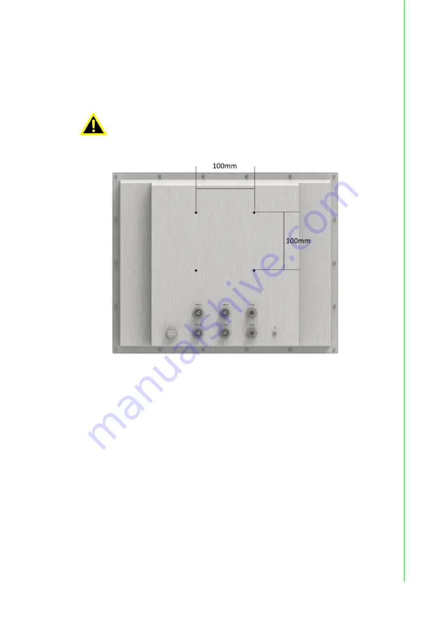
VESA Mounting 

The SPC-200 has been designed with support for the VESA mount standard which

supports  100mm  standard  VESA  dimension  holes  (Refer  to  figure  1.2.).  Use  M4

screws (Length 8mm to 10 mm).

Figure 1.2 VESA Mounting 

Warning!

Use suitable mounting apparatus to avoid risk of injury.

Summary of Contents for SPC-515 Series

Page 1: ...User Manual SPC 515 Series Stainless Steel Multi Touch Panel Computer with Intel Skylake Processor 26 20 1 02 27927818...

Page 2: ...orporation Microsoft Windows and MS DOS are registered trademarks of Microsoft Corp All other product names or trademarks are properties of their respective owners This Manual Covers the Following Mod...

Page 3: ...he cost of replacement materials service time and freight Please consult your dealer for more details If you think you have a defective product follow these steps 1 Collect all the information about t...

Page 4: ...struction manual may cause harmful interference to radio communications Opera tion of this equipment in a residential area is likely to cause harmful interference in which case the user will be requir...

Page 5: ...fety reasons the equipment should be opened only by qualified service personnel 14 If one of the following situations arises get the equipment checked by service personnel The power cord or plug is da...

Page 6: ...SPC 515 Series User Manual vi...

Page 7: ...wer Connector 8 Figure 2 3 Power Receptor with M12 Connector 9 2 2 Installing the Drivers 10 2 2 1 Installation of Touch Screen Driver 10 2 2 2 Installation of Watchdog Driver 10 2 2 3 Installation of...

Page 8: ...SPC 515 Series User Manual viii...

Page 9: ...Chapter 1 1 General Information...

Page 10: ...2 compliant to fulfill strict hygiene requirements and the enhanced front glass touch screen is rugged and shatter resistant Key features 15 XGA TFT LED LCD display Intel Skylake Intel Core U series p...

Page 11: ...onnection M12 A coding 8 pin male 2 USB Port USB 2 0 x 2 connection M12 A coding 8 pin female 1 3 3 Safety and Environment Safety FCC Class A CE certificated Environment Operating Temperature 0 50 C 3...

Page 12: ...troller USB Interface 1 6 Power Input Voltage 24VDC Typical Power Consumption 60W Typical This product is intended to be supplied by a listed power adapter or DC power source rated 24Vdc 2 5A minimum...

Page 13: ...nting The SPC 200 has been designed with support for the VESA mount standard which supports 100mm standard VESA dimension holes Refer to figure 1 2 Use M4 screws Length 8mm to 10 mm Figure 1 2 VESA Mo...

Page 14: ...SPC 515 Series User Manual 6 1 9 Dimensions and Cutout SPC 515 Weight 10kg Dimensions W x H x D 389 6 x 313 7 x 56 mm 15 33 x 12 34 x 2 2 in Figure 1 3 SPC 218 Dimensions 100 100 76...

Page 15: ...Chapter 2 2 System Setup...

Page 16: ...is man ual to make sure all items have been included Figure 2 1 Unpack the Package 2 Connect the power connector with M12 connector to the 24 VDC power lines The power lines can either be of some powe...

Page 17: ...9 SPC 515 Series User Manual Chapter 2 System Setup Figure 2 3 Power Receptor with M12 Connector 4 Plug the power lines into the system power receptor with M12 connector 5 Power on the system...

Page 18: ...SPC 218 221 will use the built in PCT touch driver in the OS if operating under Win dows 10 2 2 2 Installation of Watchdog Driver 1 Enter into Watchdog folder double click AdvWDT icon and then click N...

Page 19: ...al Chapter 2 System Setup 4 Click Finish to finish the installation 5 Select Yes I want to restart my computer now and click OK 6 After installing Watchdog driver a Watchdog Service Configuration icon...

Page 20: ...figuration icon and you can configure the Watchdog timer function 2 2 3 Installation of Graphic Driver 1 Enter into TS folder enter into graphic driver for Windows 7 Driver folder and double click set...

Page 21: ...13 SPC 515 Series User Manual Chapter 2 System Setup 3 Select Express and click Next 4 Click Accept 5 Click Finish to finish the installation...

Page 22: ...4 Installation of LAN Driver 1 Enter TS folder then go to Ethernet driver for Windows 7 Driver folder and 1 Double click setup icon then click Next under setup wizard window 2 Click Install 3 Click F...

Page 23: ...2 User can disable USB wake up function through BIOS setting as follows a Press Delete key on the keyboard to go into the BIOS setup utility then select chipset south bridge and press Enter key b Sel...

Page 24: ...SPC 515 Series User Manual 16...

Page 25: ...Chapter 3 3 Features in Windows Embedded...

Page 26: ...y finish all their changes on the system such as installing their applications or adjusting system settings Advantech provides a pair of utilities to operate EWF OSLock and OSUnLock Refer to the train...

Page 27: ...Appendix A A M12 connector I O pin definition...

Page 28: ...r A 3 USB Pin Definition with M12 Connector LAN Pin Number Signal Female M12 A 8P F LAN 1 TX_D1 2 TX_D1 3 RX_D2 4 BI_D3 5 BI_D3 6 RX_D2 7 BI_D4 8 BI_D4 RS 232 Pin Number Signal Male M12 A 8P M RS 232...

Page 29: ...515 Series User Manual Appendix A M12 connector I O pin definition A 4 Power Input Pin Definition with M12 Connector USB Pin Number Signal Male M12 A 5P M Power 1 DC 24V 2 DC 24V 3 DC 24V 4 DC 24V 5...

Page 30: ...SPC 515 Series User Manual 22...

Page 31: ...Appendix B B UI Operating Process...

Page 32: ...at http support advantech com See the process below 1 There are 2 function buttons in the lower right corner of the front panel I icon is the intelligent key while the house icon is the home key Inte...

Page 33: ...PC 515 Series User Manual Appendix B UI Operating Process Home Long press to disable enable touch function Note When touch function is disabled you ll see a message in the lower right corner of the sc...

Page 34: ...User Manual 26 4 Press Intelligent Key Intelligent Advantech Intelligent Utility A Quick start Press to add shortcut Long press the icon to perform right click until an X mark appears in upper right c...

Page 35: ...ocess B Setting Password confirmation for authority confirmation is needed when you first log in default password is 1234 without input order to active Setting Home key Select an executable file to se...

Page 36: ...28 Setting Brightness Brightness control from 1 to 8 Setting Password Change password function Note If you use other brightness setting tools such as iManager remember not to adjust below 10 percent...

Page 37: ...8 221 also provides open button code as following definition for customer s configuration to their Apps SW applications The codes are defined from general keyboard input Table B 2 Button Code Hotkeys...

Page 38: ...tions are subject to change without notice No part of this publication may be reproduced in any form or by any means electronic photocopying recording or otherwise without prior written permis sion of...

Reviews: