SmartFlex SR303
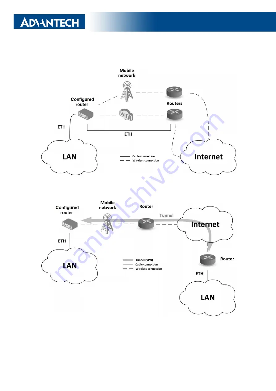
II. Backed up access to the Internet (from LAN)
Figure 2: Backed up access to the Internet
III. Secure networks interconnection or using VPN
Figure 3: Using VPN tunnel
7
Page 1: ...LTE Industrial Router SmartFlex SR303 USER MANUAL ...
Page 2: ...subject to change without notice and does not represent a commitment on the part of Advantech Advantech Czech s r o shall not be liable for incidental or consequential damages resulting from the furnish ing performance or use of this manual All brand names used in this manual are the registered trademarks of their respective owners The use of trademarks or other designations in this publication is...
Page 3: ...to the router Attention Problems that can arise in specific situations Information notice Useful tips or information of special interest Advantech Czech s r o Sokolska 71 562 04 Usti nad Orlici Czech Republic Document No MAN 0006 EN revision from June 8 2023 Released in the Czech Republic ii ...
Page 4: ... 5 7 Removal from the DIN rail 17 5 8 Description of the rear panel 18 5 9 Description of the front panel 18 5 9 1 Status indication 19 5 9 2 Power connector PWR 20 5 9 3 Antenna connector ANT DIV GPS and WiFi 22 5 9 4 SIM card reader 23 5 9 5 MicroSD card reader 24 5 9 6 Ethernet Ports ETH0 and ETH1 26 5 9 7 Power over Ethernet PoE 27 5 9 8 USB Port 29 5 9 9 I O Port 30 5 9 10 Reset 32 5 10 Inter...
Page 5: ... 3 Type tests and environmental conditions 47 7 4 Technical parameters of cellular module 48 7 5 Technical parameters of GPS 49 7 6 Technical parameters of WiFi 50 7 7 Technical parameters of I O port 50 7 8 Technical Parameters of Power over Ethernet PoE 51 7 9 Other Technical Parameters 51 8 Related Documents 52 9 Troubleshooting 53 9 1 FAQ 53 10 Customer Support 56 iv ...
Page 6: ... SWITCH and WiFi metal 11 17 Version RS232 RS485 metal 11 18 Version RS232 RS485 WiFi metal 11 19 Version RS232 RS485 ETH metal 11 20 RS232 RS485 ETH WiFi plastic 12 21 RS232 RS485 ETH WiFi metal 12 22 RS485 RS485 metal 12 23 Label examples 13 24 Basic dimensions of the router box 16 25 Default position of plastic and metal DIN rail clip 17 26 Removal from the DIN rail 17 27 SmartFlex front panel ...
Page 7: ... 36 45 Connection of jumpers 37 46 Version with RS485 RS485 interface 38 47 RS485 connector 38 48 Version with RS232 RS485 ETH interface 39 49 Ethernet connector 39 50 RS485 connector 40 51 RS232 connector 40 52 Router connection 42 53 Entering the IP address of the router 43 54 Entering login information 44 55 Router web interface 44 vi ...
Page 8: ...e 33 20 SWITCH interface parameters 34 21 Connection of RS232 connector 35 22 Connection of RS485 connector 36 23 Connection of RS422 connector 36 24 Technical specification of RS232 and RS485 37 25 Connection of RS485 connector 38 26 Connections of the Ethernet Connector 39 27 Connections of Terminal Block Connector RS485 40 28 Connections of Terminal Block Connector RS232 40 29 State indication ...
Page 9: ...ipement est convenable en Classe 1 Division 2 Groupes A B C et D endroits dangereux OU endroits non dangereux seulement AVERTISSEMENT RISQUE D EXPLOSION NE DÉCONNECTEZ PAS L ÉQUIPEMENT SAUF SI L ALIMENTATION A ÉTÉ COUPÉE OU SI L ENVIRONMEMENT EST CLASSÉ NON DANGEREUX AVERTISSEMENT RISQUE D EXPLOSION SUBSTITUTION DE TOUTE COMPOSANTE RISQUERAIT LA QUALITÉ POUR CLASSE 1 DIVISION 2 AVERTISSEMENT RISQU...
Page 10: ...ambient conditions Protect the router against dust moisture and high temperature Only routers with appropriate certification and labelling should be used in locations where flammable and explosive materials are present including gas stations chemical plants or locations in which explosives are used We remind users of the duty to observe the restrictions concerning the utilization of radio devices ...
Page 11: ... to minimize the environmental impact This product contains high quality materials and components which can be recycled At the end of it s life this pro duct MUST NOT be mixed with other commercial waste for disposal The device contains a battery Re move the battery from the device before disposal The battery in the device needs to be disposed of apart accordingly Check the terms and conditions of...
Page 12: ...ces via Ethernet The SmartFlex router can also be configured with a wide variety of port options These can be SWITCH three switched Ethernet ports RS232 RS485 422 combination of serial interfaces RS485 RS485 two RS485 serial lines RS232 RS485 ETH combination of serial interfaces and Ethernet port with higher insulation The router can be provided in either a plastic or metal casing depending upon t...
Page 13: ...eet management security system telematic telemetric remote monitoring vending and dispatcher machines 3 1 Usage of the Router The router is primarily intended for these four basic situations I Access to the Internet from LAN Figure 1 Access to the Internet from LAN 6 ...
Page 14: ...SmartFlex SR303 II Backed up access to the Internet from LAN Figure 2 Backed up access to the Internet III Secure networks interconnection or using VPN Figure 3 Using VPN tunnel 7 ...
Page 15: ...SmartFlex SR303 IV Serial Gateway Figure 4 Serial Gateway 8 ...
Page 16: ...version with interface RS232 RS485 422 2 pieces of 5 pins terminal block for RS485 only for version with interface RS485 RS485 3 pins and 4 pins terminal block for RS485 and RS232 only for version with interface RS232 RS485 ETH clip for the DIN rail printed Quick Start Guide Leaflet Figure 5 Contents of package Temperature range for power supply is reduced to 0 C to 40 C 1 These pins are designed ...
Page 17: ...r versions SIM BIN BOUT USB SD ETH WiFi 232 485 Basic version 2 x 2 x 1 x 1 x 1 x 2 x Basic version with WiFi 2 x 2 x 1 x 1 x 1 x 2 x 1 x Version with SWITCH board 2 x 2 x 1 x 1 x 1 x 5 x Version with SWITCH board WiFi 2 x 2 x 1 x 1 x 1 x 5 x 1 x Version with RS232 RS485 422 board 2 x 2 x 1 x 1 x 1 x 2 x 1 x 1 x Version with RS232 RS485 422 WiFi 2 x 2 x 1 x 1 x 1 x 2 x 1 x 1 x 1 x Version with RS2...
Page 18: ...2 Version RS232 RS485 plastic Figure 13 Ver RS232 RS485 WiFi plastic Figure 14 Version RS232 RS485 ETH plastic Figure 15 Version SWITCH metal Figure 16 Version SWITCH and WiFi metal Figure 17 Version RS232 RS485 metal Figure 18 Version RS232 RS485 WiFi metal Figure 19 Version RS232 RS485 ETH metal 11 ...
Page 19: ... The revision number is printed on the packaging and product labels The router GUI can also display the product revision under Status General System Information Product Revision Please note that the default revision Rev 1 0 is unavailable here Rev Description 1 0 Initial version revision not printed on the labels 2 0 New SIM slot type see PCN 2022 03 for details Table 2 HW Revisions History 12 ...
Page 20: ...SmartFlex SR303 5 3 Delivery identification Trade name Product name Description SmartFlex SR303 SmartFlex Router in a plastic or metal box Table 3 Delivery identification Figure 23 Label examples 13 ...
Page 21: ...er 2x SIM reader RS232 RS485 SR303 BB SR3031x3yz LTE module for EMEA 2x ETH 1x USB 2x BI 1x BO 1x microSD reader 2x SIM reader WiFi RS232 RS485 SR303 BB SR3030x4yz LTE module for EMEA 3x ETH 1x USB 2x BI 1x BO 1x microSD reader 2x SIM reader RS232 RS485 SR303 BB SR3031x4yz LTE module for EMEA 3x ETH 1x USB 2x BI 1x BO 1x microSD reader 2x SIM reader WiFi RS232 RS485 SR303 BB SR3030x6yz LTE module ...
Page 22: ... Features interfaces Box Plug type BB SR30308011 LTE module for EMEA 2x ETH 1x USB 2x BI 1x BO 1x microSD reader 2x SIM reader PoE PSE plastic European BB SR30319015 LTE module for EMEA 2x ETH 1x USB 2x BI 1x BO 1x microSD reader 2x SIM reader WiFi PoE PD plastic EU US UK AUS BB SR30309121 LTE module for EMEA 5x ETH 1x USB 2x BI 1x BO 1x microSD reader 2x SIM reader PoE PD metal European BB SR3031...
Page 23: ...es in connection with EMC according to EN 61439 1 2011 In compliance with the EN 61439 1 2011 specification it is necessary to observe the following assembly instructions for a router attached to a switchboard For whip antennas it is recommended to observe a minimum distance of 6 cm from ca bles and metal surfaces on every side in order to avoid interference When using an external antenna separate...
Page 24: ... rail according to EN 60715 standard only The default position of plastic or metal rail clip which is used for mounting the router on a DIN rail is shown in the following figure Its position can be changed on some models back or bottom When changing the position of the DIN rail clip tighten the screws with max 0 4 Nm torque Figure 25 Default position of plastic and metal DIN rail clip To remove th...
Page 25: ...he computer network PoE only for PoE PSE or PoE PD versions ETH1 RJ45 Connector for connection into the computer network PoE only for PoE PSE or PoE PD versions ANT SMA Connector for main antenna DIV SMA Connector for diversity antenna GPS SMA Connector for GPS antenna WiFi R SMA Connector for WiFi antenna only for versions with WiFi module USB USB A 2 0 Host Connector for connection of USB device...
Page 26: ...5 s Fades out 1x 2 s Fades out 1x 1 s Signal strength is good Signal strength is fair2 Signal strength is poor3 For value ranges of signal strength see Configuration manual chapter Mobile WAN Status DAT Red Blinking Cellular communication is in progress IN0 Green On The first binary input is active IN1 Green On The second binary input is active OUT Yellow On The binary output is active ETH0 ETH1 G...
Page 27: ...cables with minimum wire size nominal cross section 0 5 square mm for power supply The power supply for the router must be between 10 V to 60 V DC supply Protection against reversed polarity without signaling is built into the router Note The protection against reversed polarity is lost if the negative pole is grounded Circuit example Figure 29 Connection of power supply Note for PoE See Chapter 5...
Page 28: ...de is a router mode where the router is in sleep mode with minimal power consumption The router can be woken up from this mode by a signal applied to the BIN1 input or after a predetermined period of time Putting the router into LPM mode can be done using the lpm command see Commands and Scripts application note for more details Consumption in LPM mode may vary depending on the configuration of th...
Page 29: ...ird connector GPS is intended for a GPS antenna the router supports active GPS antennas An R SMA connector named WiFi is designed for the connection of a WiFi antenna available only for versions with a WiFi module The router can not operate without a main antenna connected through the port marked as ANT The DIV celullar antenna is required for the MIMO DL functionality An SMA connector is used for...
Page 30: ...usted Supported type of SIM cards Mini SIM 2FF dimensions 25 0 x 15 0 x 0 76 mm Changing the SIM card Always disconnect the router from the power supply before handling the SIM card To remove the SIM card use the flat end of a spudger or your fingernail press the SIM card slightly into its slot until you hear a click After hearing this click release the card and it will pop out of its slot Remove ...
Page 31: ...fications of microSD card Changing the microSD card To remove the microSD card use the flat end of a spudger or your fingernail press the microSD card slightly into its slot until you hear a click After hearing this click release the card and it will pop out of its slot Remove the microSD card and push any other microSD card into the slot until it clicks into place Figure 32 MicroSD card Mounting ...
Page 32: ...o to mnt directory use the mount command mount dev mmcblk0p1 mnt For more information about the commands for creating mounting checking and unmounting a file system on a microSD card see the application note for Ext4_tools router app 25 ...
Page 33: ...oE negative pole Table 13 Ethernet connector pinout Figure 33 Ethernet connector The crossover UTP cable Ethernet cable plugs into the RJ45 connector labeled as ETH0 or ETH1 see the figure below Figure 34 Connection of Ethernet cable The insulation strength of Ethernet ports from each other and from the rest of the router grounding is dependent on the router version Router Version Insul Strength f...
Page 34: ...both Ethernet ports ETH0 and ETH1 The PoE PSE version allows the router to power other devices over the Ethernet The PoE PD version enables the router to be powered by another PoE PSE device over the Ethernet PoE PD Figure 35 PoE PD usage The PoE PD parameters can be found in Chapter 7 8 The POE LED on the front panel of the router lights up green when voltage is present on an Ethernet port so the...
Page 35: ...dicates insufficient power or voltage through the PWR connector When a device is being powered from the router the POE LED will be blinking green Yellow blinking is shown for an overload the powered device is using too much power or a short circuit incorrect wiring of the cable or of the device without PoE support You can enable or disable the PoE PSE feature separately on the ETH0 and ETH1 ports ...
Page 36: ... high current The port is enabled again after the reboot of the router Mounting USB Flash Drive to the System It is necessary to mount the USB flash drive to be able to access it in the system of the router Follow these steps to mount the drive Use the dmesg command to see the list of recently connected devices In the output of the command find out the entry for the microSD card for example sda sd...
Page 37: ...put is open in the default configuration The isolation strength is 1 5 kV The pins are isolated from each other with the same strength The input circuits are bipolar and allow connection as needed with common plus or minus according to the connection of an external voltage Binary inputs Characteristics of inputs Logical 0 1 Voltage Current Web interface status log 1 max 3 V 0 4 mA Off log 0 min 5 ...
Page 38: ...ry output parameters 60 V AC 300 mA 60 V DC 300 mA The current of the binary output is limited by a resettable fuse 300 mA Binary inputs and output connections Binary inputs and output connections example Figure 39 Binary connection 31 ...
Page 39: ... button Figure 40 Router reset Before resetting the router it is recommended to back up the router configuration settings see Configuration manual because resetting the router will return all configuration set tings to their default states It is important to distinguish between the router reset and reboot Action Router behavior Invoking events Reboot Turns off and then turns on the router Disconne...
Page 40: ...ny port on the SWITCH interface and transmits them on other ports of the SWITCH interface Each port can transmit frames inde pendently on the other ports State indication is displayed separately on each connector These router versions comply with the standards and temperature ranges stated in Chap 7 1 except for having a lower maximum operating temperature which is 70 C Figure 41 Version with SWIT...
Page 41: ...lex SR303 Technical specification of Ethernet IEEE 802 3 Ethernet interface IEEE 802 3 standard Maximum data rate 100 Mbps Max total cable length 300 Bd 200 nF km 100 m Table 20 SWITCH interface parameters 34 ...
Page 42: ...ce When connecting counterpart terminal block connectors included in package with the router use cables with nominal cross section 0 2 to 1 0 square mm 30 to 16 AWG Recommended stripping length is 5 mm For M2 captive screws the screw driver 0 5 x 3 mm is recommended Tighten the screws with 0 3 Nm torque Connection of RS232 connector Pin Signal Description Direction 1 CTS Clear To Send Output 2 RTS...
Page 43: ...tion Direction 1 RxD RS422 Output 2 RxD RS422 Output 3 TxD RS422 Input 4 TxD RS422 Input Table 23 Connection of RS422 connector Figure 44 RS485 422 connector The selection of either RS485 or RS422 can be performed by using jumpers on the board The points where jumpers have to be mounted are shown on the port see the fig ure below Three jumpers are required for the RS485 interface or one jumper for...
Page 44: ...r of devices on RS485 bus 32 Max output current on RS485 bus 60 mA Max data rate 230400 bps on RS232 230400 bps on RS485 Max total cable length 300 Bd 200 nF km RS232 20 m RS485 1200 m Table 24 Technical specification of RS232 and RS485 The termination resistor can be activated directly on the port board using a jumper termination resistor is part of the port board 37 ...
Page 45: ...t terminal block connectors included in package with the router use cables with nominal cross section 0 2 to 1 0 square mm 30 to 16 AWG Recommended stripping length is 5 mm For M2 captive screws the screw driver 0 5 x 3 mm is recommended Tighten the screws with 0 3 Nm torque Figure 47 RS485 connector Connection of RS485 connector Pin Description Direction 1 RS485 A Input Output 2 RS485 B Input Out...
Page 46: ...om the rest of the router State indication is displayed by LEDs above each connector as shown in the table below These router versions comply with the standards and temperature ranges stated in Chap 7 1 Figure 48 Version with RS232 RS485 ETH interface Connection of ETH connector Pin Signal Description Direction 1 TXD Transmit Data positive pole Input Output 2 TXD Transmit Data negative pole Input ...
Page 47: ...ground 2 TxRx RS485 B Input Output 3 TxRx RS485 A Input Output Table 27 Connections of Terminal Block Connector RS485 Signal ground is isolated from the router s ground Figure 50 RS485 connector The termination resistor can be activated directly on the port board using a jumper termination resistor is part of the port board Connection of RS232 connector Pin Signal Description Direction 1 AUX 5 V 5...
Page 48: ...ow LED Indicates Transmit data Table 29 State indication of the RS232 RS485 ETH interface Technical specification of RS232 RS485 bus and Ethernet IEEE 802 3 ETH2 RS485 and RS232 interface Max operating RS232 bus current 15 mA Max number of devices on RS485 bus 32 Max output current on RS485 bus 60 mA Max data rate 230400 bps on RS232 230400 bps on RS485 100 Mbps on ETH2 Max total cable length 300 ...
Page 49: ...peration it is necessary to connect all of the components that are required to run your applications Don t forget to insert a SIM card The router can not operate without a connected antenna SIM card and power supply If the antenna is not connected the router may be damaged Figure 52 Router connection 42 ...
Page 50: ...e accessed by entering the IP address of the router into the web browser The default IP address of the router is 192 168 1 1 Attention it is necessary to use HTTPS protocol for secure communication over a network Figure 53 Entering the IP address of the router By default configuration may be performed only by the user root The default password is printed on the router s label 1 Change the default ...
Page 51: ...ex SR303 Figure 54 Entering login information Figure 55 Router web interface A detailed description of the router settings in the Web interface can be found in the Configuration manual for SmartFlex routers 44 ...
Page 52: ...ative humidity non condensing 0 to 95 relative humidity non condensing Altitude Operating 2000 m 70 kPa Degree of protection IP30 Supply voltage 10 to 60 V DC Battery for RTC CR1225 Consumption Idle Average Peak Sleep mode 2 5 W 4 W 11 W 10 mW Dimensions 55 x 97 x 125 mm 2 17 x 3 82 x 4 92 DIN 35 mm EN 60715 Weight Plastic box Metal box approximately 170 g 0 37 lbs depends on interface approximate...
Page 53: ...08 13 ETSI EN 300 328 ETSI EN 301 893 EMC ETSI EN 301 489 1 ETSI EN 301 489 1 ETSI EN 301 489 19 ETSI EN 301 489 52 ETSI EN 301 489 17 Safety IEC 62368 1 EN 62311 UL C1D2 UL E486108 E Mark EMC for de vices in transportation E Mark homologation number 10R 04 7737 National CE UKCA Brazil Anatel 00176 19 05739 Table 32 Standards and Regulations Excluding versions with PoE PSE or versions with RS232 R...
Page 54: ...t A 2 kV L to GND crit A RF conducted EN 61000 4 6 All ports 10 V m crit A 0 15 80 MHz Radiated emission EN 55022 Enclosure Class B Conducted emission EN 55022 DC power ports Ethernet ports Class B Class B Power frequency magnetic field EN 61000 4 8 Enclosure 160 A m crit A Dry heat EN 60068 2 2 75 C 40 rel humidity Cold EN 60068 2 1 40 C Damp heat EN 60068 2 78 95 rel humidity 40 C Vibration EN 6...
Page 55: ...UL CS bit rate 64 kbps DL 64 kbps UL W CDMA FDD standard Supported frequencies B8 900 MHz B3 1800 MHz B1 2100 MHz Max power typical 24 dBm GPRS EDGE parameters Bit rate 237 kbps DL 59 2 kbps UL GPRS multislot class 10 CS 1 to 4 EDGE multislot class 12 CS 1 to 4 MCS 1 to 9 Supported frequencies 900 1800 MHz Max power typical 26 33 dBm GPRS EDGE power classes EGSM 900 Class 4 33 dBm GSM 1800 Class 1...
Page 56: ...Hot start 1 s Warm start 29 s Cold start 32 s Accuracy Horizontal 2m 50 5 m 90 Altitude 4 m 50 8 m 90 Velocity 0 2 mps Table 35 Technical parameters of GPS Tracking sensitivity is the lowest GPS signal level for which the device can still detect an in view satellite 98 of the time when in sequential tracking mode Acquisition sensitivity is the lowest GPS signal level for which the device can still...
Page 57: ...Fi RX Sensitivity 96 3 dBm AP maximum users 10 users WiFi module supports multi role operation in STA and AP Multi role does not affect the maximum number of users Table 36 Technical parameters of WiFi 7 7 Technical parameters of I O port Characteristics of inputs Logical 0 1 Voltage Current Web interface status log 1 max 3 V 0 4 mA Off log 0 min 5 V 0 7 mA On log 0 type 12 V 2 mA On log 0 max 60 ...
Page 58: ...E PD parameters for opposite PSE Input voltage range 42 5 57 V Power available 25 50 W Maximum current 600 mA Table 38 PoE PD parameters for opposite PSE PoE PSE parameters Power supply needed 44 57 V 65 W Power available 2x 25 50 W ETH0 ETH1 Table 39 PoE PSE parameters 7 9 Other Technical Parameters Parameter Description CPU power 2 DMIPS per MHz Flash memory 256 MB RAM 512 MB M RAM 128 kB Table ...
Page 59: ...SmartFlex SR303 8 Related Documents 1 Advantech Czech Configuration Manual for SmartFlex Routers 52 ...
Page 60: ... status page If the signal power is weak you will have to use a better antenna If the neighbouring cells have a similar signal strength you will need to use a directional antenna For proper operation the signal levels have to be good Try to enable automatic ping from the router which will check the connection when there are no data running and in the case of a failed ping restart the connection Th...
Page 61: ... You can verify NAT using ping to your server with static address and then compare with router s IP address You can verify a Firewall by accessing remotely to the router s Web interface The operator may not provide the address of DNS server and without DNS server s address it is impossible to connect to the dyndns org server The following mes sages will be shown in the System Log DynDNS daemon sta...
Page 62: ...routers only You can use SFTP on all routers to transfer files to from the router If having troubles with FTP on v2 routers make sure you have FTP enabled Configuration section Services FTP Then you can connect with any client on port 21 with name and password same as for the Web interface If having troubles with SFTP make sure you have SSH enabled Configuration section Services SSH Then you can c...
Page 63: ...u Web www advantech com Customer Support for NAM Advantech B B SmartWorx 707 Dayton Road Ottawa IL 61350 USA Phone 1 800 346 3119 Monday Friday 7 a m to 5 30 p m CST Fax 1 815 433 5109 E mail support advantech bb com Web www advantech bb com Customer Support for Asia Phone 886 2 2792 7818 1299 Monday Friday 9 a m to 5 30 p m UTC 8 Fax 886 2 2794 7327 E mail icg support advantech com tw Web www adv...
Page 64: ...complies with Radio Equipment Regulations 2017 S I 2017 No 1206 We Advantech Czech s r o declare that the radio equipment narrated in this user s manual complies with Directive 2014 53 EU The full text of the EU Declaration of Conformity is available at the following internet address icr advantech cz eudoc ...