PPC-L128T User Manual
8
2.1
A Quick Tour of the Panel PC
Before you start to set up the panel PC, take a moment to become familiar with the
locations and purposes of the controls, drives, connectors and ports, which are illus-
trated in the figures below.
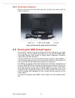
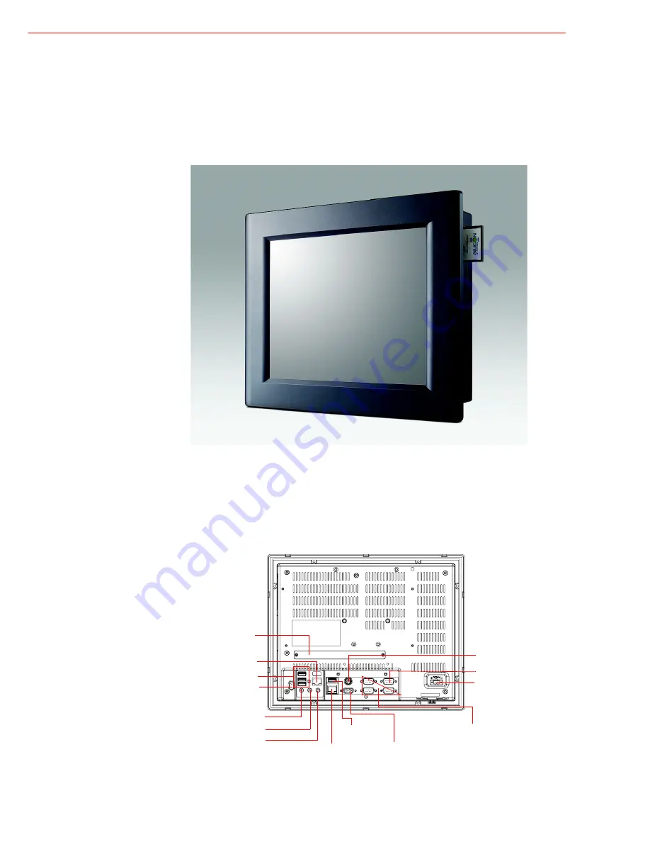
When you place the panel PC upright on the desktop, its front panel appears as
shown in Figure 2.1.
Figure 2.1 Front view of PPC-L128T panel PC
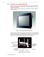
When you turn the panel PC around and look at its rear cover, you will find the I/O
section as shown in Fig. 2.2. (The I/O section includes vari- ous I/O ports, including
serial ports, the Ethernet port, USB ports, the Line-in/Line-out jack, and so on.) The
battery door cover is at the bottom of the panel PC, as shown in Fig. 2.4.
Figure 2.2 Rear view of Panel PC
PCI/
PCIe
expansion
slot cover
Ethernet jack
USB 2.0 x 3
Main power switch
Line-in jack
Mic-in jack
Line-out jack
Ethernet jack
USB 2.0
VGA port
PS2 mouse
and keyboard
GPIO port
DC inlet
Serial ports
Summary of Contents for PPC-L128T
Page 1: ...User Manual PPC L128T Intel AtomTM N270 Processor based Fanless Panel PC with 12 1 TFT LCD...
Page 6: ...PPC L128T User Manual vi...
Page 14: ...PPC L128T User Manual 6...
Page 20: ...PPC L128T User Manual 12...
Page 24: ...PPC L128T User Manual 16...
Page 30: ...PPC L128T User Manual 22...

