5
PPC-4150W User Manual
Chapter 1
G
eneral
Information
1.3
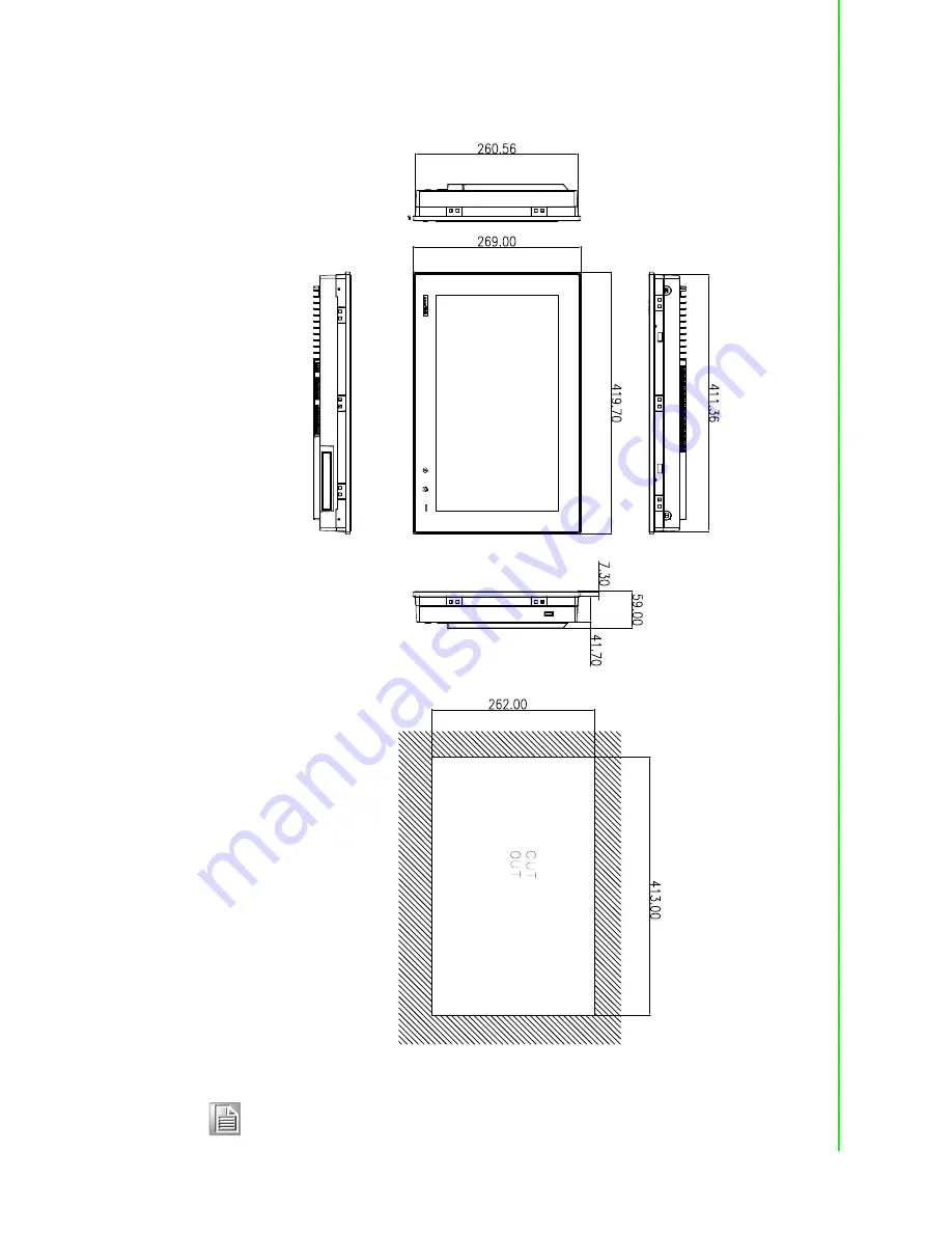
Dimensions
Figure 1.1 PPC-4150W dimensions
Note!
Supports VESA 100 x 100 mm; please use M4 screw, 6 mm depth(maximum).
Use suitable mounting apparatus to avoid risk of
injury.
Page 1: ...User Manual PPC 4150W Intel Atom D2550 processor based microcomputer with 15 6 color TFT LCD display...
Page 2: ...antech assumes no liability under the terms of this warranty as a consequence of such events Because of Advantech s high quality control standards and rigorous testing most of our customers never need...
Page 3: ...uctions may cause harmful inter ference to radio communications However there is no guarantee that interference will not occur in a particular installation If this equipment does cause harmful interfe...
Page 4: ...our any liquid into an opening This may cause fire or electrical shock 13 Never open the equipment For safety reasons the equipment should be opened only by qualified service personnel 14 If one of th...
Page 5: ...any components on the CPU card or other cards while the PC is on Disconnect power before making any configuration changes The sudden rush of power as you connect a jumper or install a card may damage...
Page 6: ...PPC 4150W User Manual vi...
Page 7: ...f I O interfaces 9 Figure 2 4 Grounding screw 9 Figure 2 5 PCI expansion slot 9 2 2 Installation Procedures 10 2 2 1 Connect Power Cable 10 Figure 2 6 Connect power cable 10 2 2 2 Connect Keyboard and...
Page 8: ...stallation 19 2 12 Cradle Installation Description 20 Chapter 3 Jumper Configuration 21 3 1 Jumper Connectors 22 Figure 3 1 PCM 8208 front view 22 3 2 External COM PORT DIO Switch and PIN Definition 2...
Page 9: ...Chapter 1 1 General Information This chapter gives background information on PPC 4150W panel PC Sections include Introduction Specifications Dimensions...
Page 10: ...mobility For safety consideration PPC 4150W provides 2 Giga LAN configu ration In addition 4 serial ports and 5 USB V2 0 interfaces make the product suit for all kinds of advanced applications 1 2 Sp...
Page 11: ...enix power port 1 x Power switch Expansion Slot 1 x PCIe x1 standard 1 x PCI in the accessory box Additional Expansion Slot 1 x Mini PCIe long card slot and 1 x mSATA card slot System Win XPE WES 7 WI...
Page 12: ...ns are as follows EMC BSMI CE FCC Class B Safety CB CCC UL Front Panel IP Grade IP65 Test Software Test Configuration Test System Burn in 7 0 Memory Transcend DDR3 1333 SODIMM 4 GB x 1 HDD Seageat 500...
Page 13: ...er Manual Chapter 1 General Information 1 3 Dimensions Figure 1 1 PPC 4150W dimensions Note Supports VESA 100 x 100 mm please use M4 screw 6 mm depth maximum Use suitable mounting apparatus to avoid r...
Page 14: ...PPC 4150W User Manual 6...
Page 15: ...ions include Quick Installation Guide Inslation Procedures Install Memory Install HDD Install Mini SATA Install Wireless LAN Install Expansion Card AT ATX Function Switch Grounding Installation Hook I...
Page 16: ...ions and purposes of the controls drives connectors and ports which are illus trated in the figures below When you place the panel PC upright on the desktop its front panel appears as shown in Figure...
Page 17: ...I O interfaces Figure 2 3 Location of I O interfaces A Line out Mic in B 2 x Giga Ethernet ports C 4 x USB 2 0 D DIO E VGA F COM 1 3 4 ports COM2 RS232 422 485 port G DC power port 12 30 V H Power bu...
Page 18: ...procedures below 1 Connect the female end of the power cable to panel PC s DC socket 2 Connect the male end of the power cable to power outlet Figure 2 6 Connect power cable 2 2 2 Connect Keyboard and...
Page 19: ...Remove the screws as indicated in the red circle See Fig 2 11 and take out the CPU cooler Figure 2 7 Figure 2 8 Figure 2 9 Figure 2 10 Note The black and grey lumps as indicated in the red circle of F...
Page 20: ...Fig 2 13 2 Take down the HDD bracket from the reinforced board See Fig 2 14 3 Install the HDD see Fig 2 15 and take out the 4 screws from the accessory box to fix the HDD 4 Lock the HDD bracket and t...
Page 21: ...M2 5x4 screws from the accessory box to fix it 3 Return the rear cover and reinforced board 2 6 Install Wireless LAN Card 1 Please follow the procedures in Section 2 3 and 2 4 to open the rear cover...
Page 22: ...ble end and screws cushions See Fig 2 24 4 Lock the bracket and connect the cable to the wireless LAN card See Fig 2 25 5 Take down the two plugs in the left and right sides of the rear cover See Fig...
Page 23: ...rcle in Fig 2 28 and install the expansion card 2 The original machine provides PCIE riser card PCM 939 see Fig 2 29 and PCI riser card PCM 938 is provided in the accessory box for additional use See...
Page 24: ...anual 16 2 8 AT ATX Function Switch Switch is built in the machine by which you can choose AT ATX function without removing the rear cover Figure 2 30 Figure 2 31 Figure 2 32 Figure 2 33 ATX mode Figu...
Page 25: ...p 2 9 Grounding Installation Loosen the screws take down the plastic cover plug in the grounding cable and then fix the screws See Fig 2 35 Fig 2 38 Figure 2 35 Figure 2 36 Figure 2 37 Figure 2 38 Not...
Page 26: ...ow Figure 2 39 Hook Installation 33 PPC 4150W Panel Installation Guide Wallmount Installation Bracket Put the machine into the cabinet and prepare wallmount installation bracket Put the plastic plug i...
Page 27: ...ion Users can independently complete the panel wallmount installation by quick installa tion Guide Please follow the procedures below 1 Loosen the two screws at the bottom side see the figure below 2...
Page 28: ...10 Hook Installation 2 12 Cradle Installation Description Note It is recommend that the mount thickness is smaller than 2 mm 0 079 according to quick installation guide For other situations the recom...
Page 29: ...Chapter 3 3 Jumper Configuration Sections include Jumper Connectors Peripheral COM Port DIO Switch and Pin Definitions...
Page 30: ...w P3 P4 P5 P6 Interface Function JP1 Clear CMOS CN58 RS422 120 ohm resistor selection COM2 JP1 Image Clear CMOS 1 3 P3 Clear CMOS 3 5 P4 Clear CMOS Default CN58 Image RS422 120 ohm resistor selection...
Page 31: ...set as RI signal in COM port by default and selected as charged pins by BIOS 5 V 12 V see Section 4 2 4 which can be used by the peripherals COM2 The operation mode can be either RS232 422 485 selecte...
Page 32: ...Pin Definition Port Function Pin RS232 RS422 RS485 1 DCD 422_TXD 485_Data 2 RXD 422_TXD 485_Data 3 TXD 422_TXD 4 DTR 422_TXD 5 GND GND 6 DSR 7 RTS 8 CTS 9 RIC Port Function Pin DIO 1 GPIO0 2 GPIO1 3...
Page 33: ...Chapter 4 4 Software Configuration Sections include Install Drivers BIOS Setup Program...
Page 34: ...he CD ROM Windows 7 All drivers needed to install for Windows 7 Windows XP All drivers needed to install for Windows XP PPC HotKeyUtility The utility for front bezel i Key and Home Key For the specifi...
Page 35: ...anual Chapter 4 Software Configuration 4 2 BIOS Setup 4 2 1 Enter BIOS Start the computer and press Delete key to enter BIOS Press F4 to save and exit after any configuration or the configuration won...
Page 36: ...PPC 4150W User Manual 28 4 2 2 Display Brightness Adjustment 1 Select Host Bridge under Chipset 2 Then select Intel IGD Configuration...
Page 37: ...CD Brightness Control is configured as Manual Mode by default Select Brightness Manual Control under Brightness Control and there will be 6 options Note If you want to adjust brightness through AP in...
Page 38: ...50W User Manual 30 4 2 3 COM2 Mode Selection RS232 422 485 1 Select Super IO Configuration under Advanced 2 Select Serial Port 2 Configuration and then select the operation mode of COM2 by Serial Port...
Page 39: ...er 4 Software Configuration 4 2 4 COM1 COM2 Pin9 Function Selection 1 Select Super IO Configuration under Advanced 2 Select the needed COM port serial Port 1 2 Configuration then select Pin9 function...
Page 40: ...PPC 4150W User Manual 32 4 2 5 Wake Up by LAN 1 Select ACPI Settings under Advanced 2 Set Power Saving as Disabled and set Power On by PCIE Wake as Enabled...
Page 41: ...he configuration and exit the OS 4 Right click Computer and click Manage then open Computer Management 5 Click Network adapters in Device Manage then right click and select the needed LAN port then se...
Page 42: ...PPC 4150W User Manual 34 6 Select Realtek PCIe GBE Family Controller Properties under Power Manage ment and check Allow this device to wake the computer...
Page 43: ...35 PPC 4150W User Manual Chapter 4 Software Configuration...
Page 44: ...tions are subject to change without notice No part of this publication may be reproduced in any form or by any means electronic photocopying recording or otherwise without prior written permis sion of...