background image

13

PPC-3151 User Manual

Chapter 2

S

ystem

Installation

and

S

etup

4.

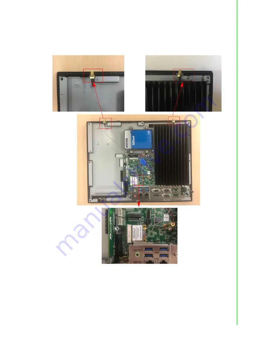
Please refer to the below to connect the cables of wireless LAN card module to 
antenna bracket. Note the installation direction of cable end, screw caps and 
washers. To make the antenna installation easier, please firstly remove two 
brackets marked with the red rectangles, and then replace them when the instal-
lation is completed.

Summary of Contents for PPC-3151

Page 1: ...User Manual PPC 3151 Intel Core i Processor Based Micro Computer with a 15 Color TFT LCD Display...

Page 2: ...Advantech assumes no liability under the terms of this warranty as a consequence of such events Because of Advantech s high quality control standards and rigorous testing most of our customers never n...

Page 3: ...uctions may cause harmful inter ference to radio communications However there is no guarantee that interference will not occur in a particular installation If this equipment does cause harmful interfe...

Page 4: ...t For safety reasons the equipment should be opened only by qualified service personnel 14 If one of the following situations arises get the equipment checked by service personnel The power cord or pl...

Page 5: ...any components on the CPU card or other cards while the PC is on Disconnect power before making any configuration changes The sudden rush of power as you connect a jumper or install a card may damage...

Page 6: ...PPC 3151 User Manual vi...

Page 7: ...cting Power Cord 8 2 2 2 Connecting Keyboard and Mouse 8 2 2 3 Switching on the Panel PC 8 2 3 Installing Memory 9 2 4 Installing HDD 10 2 5 Installing M 2 11 2 6 Installing Wireless LAN Card 12 2 7 I...

Page 8: ...PPC 3151 User Manual viii...

Page 9: ...Chapter 1 1 Overview This chapter gives background information on the PPC 3151 panel PC Sections include Introduction Specifications Dimensions...

Page 10: ...T LCD LED backlight Max Resolution 1024 x 768 Color 16 7M Dot Pitch 0 297 x 0 297 mm Viewing Angle 80 Left 80 Right 70 Up 70 Down Typ Luminance 400 cd m2 Typ Contrast 700 Typ Backlight Life 50 000 hrs...

Page 11: ...Note 1 Type 5 point projective capacitive Light Transmission 88 5 Controller USB interface Operating temperature 0 50 C 32 122 F SSD 0 45 C 32 113 F HDD Storage Temperature 40 60 C 40 140 F Relative...

Page 12: ...PPC 3151 User Manual 4 1 3 Dimensions Note Screw specification M4 hole depth is 8 mm for maximum Use suitable mounting apparatus to avoid risk of injury...

Page 13: ...Sections include A Quick Tour Installation Procedures Replacing Memory Installing HDD Installing M 2 Installing Wireless LAN Installing Expansion Card Adjusting AT ATX Functions Grounding Installing H...

Page 14: ...location and function of each control key driver connector and port please refer to the following content and figures When the panel PC is placed on the desk its front panel is shown as Figure 2 1 Fi...

Page 15: ...on slot for optional module 5 Speaker left right 6 Hooking holes for panel installation ten holes I O connectors Figure 2 3 I O Connectors A PCI PCIE expansion slots x 4 B Line out Mic in C 4 x USB 3...

Page 16: ...2 pin connector into the DC inlet of the panel PC 2 Connect power cord with power adapter with the 3 pin female connector Figure 2 4 Connecting Power Cord 2 2 2 Connecting Keyboard and Mouse Connect...

Page 17: ...ing Memory 1 Unfasten the screws marked with red circles see below left figure 2 Pop up the hook marked with a red oval see below right figure to remove the rear cover 3 Unfasten the screws indicated...

Page 18: ...r 2 3 to remove the rear cover Unfasten the screws marked with red circles and remove VESA holder below left then take out the HDD bracket below right 2 Take out 4 screws see below from the accessory...

Page 19: ...cedures in Chapter 2 3 and 2 4 to remove rear cover and VESA holder 2 Unfasten the screws marked with red circles and then fix M 2 to the location marked with a red rectangle Note Please note the pin...

Page 20: ...ve rear cover and VESA holder 2 The installation of a full size card is shown as below Unfasten the screws marked with rec circles and then secure the card to the location with a red rect angle 3 The...

Page 21: ...onnect the cables of wireless LAN card module to antenna bracket Note the installation direction of cable end screw caps and washers To make the antenna installation easier please firstly remove two b...

Page 22: ...14 5 Remove two plugs on the rear cover as shown in the below 6 Then replace the rear cover and install the antenna of wireless LAN card module Note Advantech wireless LAN card module PN PPC WLAN A1E...

Page 23: ...a PCIE riser card and a PCI riser card is also provided in the accessory box for additional use 2 8 Adjusting AT ATX Functions You can adjust AT or ATX function by the internal switch indicated by th...

Page 24: ...Hook Please refer to the below figure Hook Installation Method Place the PC into the cabinet and prepare the hook Put the hook into the hook hole in the direction shown as above to hook the PC Fasten...

Page 25: ...tallation Please follow the below procedures to complete the wall mount by yourself 1 Unfasten the two screws at the bottom as shown in below 2 Please refer to the below figure to place and push the p...

Page 26: ...0 Installing Hook to fasten the hook screw to firmly secure the panel PC Note It is recommended that the panel inlaid depth should be less than 2mm 0 079 according to Quick Installation Guide In other...

Page 27: ...Chapter 3 3 Jumper and Switch Settings Sections include Jumpers and Connectors External COM Port DIO Switch and Pin Assignments...

Page 28: ...Jumpers and Connectors Connector Function CN12 GPIO CN18 COM Pin9 power selection CN22 Power button SW2 AT ATX selection JP5 Clear CMOS JP5 Icon Clear CMOS 1 2 P9 Normal Default 2 3 P10 Clear CMOS P9...

Page 29: ...Settings CN18 COM1 2 RI type selection 1 3 2 4 P9 P10 COM1 COM2 RI Default 3 5 4 6 P11 P12 COM1 COM2 5V 7 9 8 10 P13 P14 COM1 COM2 12V P9 P10 P11 P12 P13 P14 CN12 Pin Signal 1 GND 2 GPIO4 3 GPIO0 4 G...

Page 30: ...00 mA 5V Max 500 mA COM3 RS422 485 supports isolation voltage of 1000 VDC which can be selected by BIOS UART RS485 auto flow control COM5 supports RS485 auto flow control function When enabling the RS...

Page 31: ...Chapter 4 4 Software Setup Sections include Installing Drivers BIOS Setup Utility...

Page 32: ...elect the driv ers to be installed based on the OS you use Please go to Advantech official website to get the latest versions of drivers http www advantech com cn 4 2 BIOS Setup Utility 4 2 1 Entering...

Page 33: ...51S User Manual Chapter 4 Software Setup 4 2 2 LCD Brightness Adjustment 1 Select System Agent SA Configuration under Chipset tab 2 Then choose Graphics Configuration under System Agent SA Configura t...

Page 34: ...PPC 3151 User Manual 26 3 Select LCD Control under Graphics Configuration 4 Select Brightness Manual Control under Brightness Control and there will be 6 brightness options to choose...

Page 35: ...er Manual Chapter 4 Software Setup 4 2 3 COM5 Mode RS422 485 Selection 1 Select NCT6106D Super IO Configuration under Advanced tab 2 Then choose Serial Port5 Configuration under NCT6106D Super IO Conf...

Page 36: ...PPC 3151 User Manual 28 3 Click Serial Port 5 Configuration item to choose the operating mode of COM5 4 2 4 Wake up by LAN 1 Select PCH IO Configuration under Chipset tab...

Page 37: ...ware Setup 2 Set Deep Sleep as Disabled Then set Wake On By PCIE Wake and Wake on By LAN1 219LM as Enabled 3 Save all the settings and exit Then enter the OS 4 Right click on Computer and select Manag...

Page 38: ...s Then right click on the LAN port you want to use and select Properties to pop up Intel R Ethemet window 6 In Intel R Ethemet window go to Power Management tab and check the boxes of Work On Magic Pa...

Page 39: ...Appendix A A RoHS List...

Page 40: ...Others X O O O O O O Represent the concentration for this hazardous substance in all homogeneous materials of the part Comply with the limit of the standard of GB T 26572 X Represent the concentratio...

Page 41: ...33 PPC 3151 User Manual Appendix A RoHS List...

Page 42: ...tions are subject to change without notice No part of this publication may be reproduced in any form or by any means electronic photocopying recording or otherwise without prior written permis sion of...

Reviews: