


PPC-3060S User Manual
34
4.1
Installing Divers
When you install the OS in the panel PC for the first time, you should also install the
corresponding drivers to make sure all the functions work properly.
You can download the drivers from the below ling:
http://www.advantech.com
4.2
BIOS Setup Program
4.2.1
Update BIOS
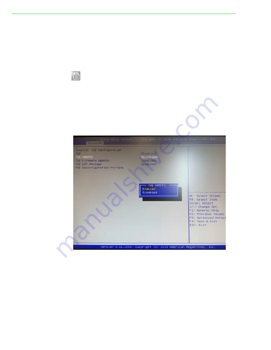
1.
When entering the BIOS menu, select "Advanced
→
Security configuration
→
TXE HMRFPO
→
enable".
2.
Restart the computer.
3.
Execute AFUDOS 8211BIOS.bin /P /B /N /X /ME.
4.
Power on the system again after it is powered off.
5.
The BIOS is then updated.
Note!
Before Windows 8.x or Android is installed, first change the BIOS set-
tings as explained in the OS Selection section; otherwise, the installa-
tion will fail. If Windows 7 is installed, it is not necessary to change the
BIOS settings.
Summary of Contents for PPC-3060S
Page 6: ...PPC 3060S User Manual vi...
Page 12: ...PPC 3060S User Manual 4 1 6 Dimensions Figure 1 4 PPC 3060S Dimension...
Page 40: ...PPC 3060S User Manual 32...
Page 41: ...Chapter 4 4 Software Setup Sections include Installing ng Drivers BIOS Setup Program...
Page 53: ...Appendix A A BSMI RoHS...
Page 55: ...Appendix B B China ROHS...
Page 57: ...Appendix C C Watchdog Timer Programming Example...


