background image

Startup Manual 2

ST

AR

TUP MANUAL

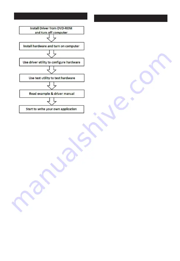
Hardware Installation

1.  Turn off your computer and unplug the power cord 

and cables. TURN OFF your computer before install-

ing or removing any components on the computer.

2.  Remove the cover of your computer.
3.  Remove the slot cover on the back panel of your 

computer.

4.  Touch the metal part on the surface of your computer 

to neutralize the static electricity that might be on 

your body.

5.  Adjust DIP switch SW1 on board to set the card’s 

board ID.

6.  Insert the PCI-1752USO card into a PCI slot. Hold 

the card only by its edges and carefully align it with 

the slot. Insert the card firmly into place. Use of 

excessive force must be avoided; otherwise, the card 

might be damaged.

7.  Fasten the bracket of the PCI card on the back panel 

rail of the computer with screws.

8.  Connect appropriate accessories (100-pin cable, wir-

ing terminals, etc. if necessary) to the PCI card.

9.  Replace the cover of your computer chassis. Re-

connect the cables you removed in step 2.

10.  Plug in the power cord and turn on the computer.

Software Installation

Summary of Contents for PCI-1752USO

Page 1: ...ables are used for external wiring We recommend the use of shielded cables This kind of cable is available from Advantech Please contact your local supplier for ordering information Notes For more information on this and other Advantech products please visit our websites at http www advantech com For technical support and service http www advantech com support This startup manual is for PCI 1752US...

Page 2: ...itch SW1 on board to set the card s board ID 6 Insert the PCI 1752USO card into a PCI slot Hold the card only by its edges and carefully align it with the slot Insert the card firmly into place Use of excessive force must be avoided otherwise the card might be damaged 7 Fasten the bracket of the PCI card on the back panel rail of the computer with screws 8 Connect appropriate accessories 100 pin c...

Page 3: ...Channel Freeze function input I O Connector Signal Description PIN Name Reference Direction Description IDO 00 15 PCOM0 Output Isolated digital output of group 0 IDO 16 31 PCOM1 Output Isolated digital output of group 1 IDO 32 47 PCOM2 Output Isolated digital output of group 2 IDO 48 63 PCOM3 Output Isolated digital output of group 3 PCOM0 Output Common pin for IDO00 IDO15 for inductive loads PCOM...

Page 4: ...he status of isolated digital output channels are selected by jumper JP1 The following table shows the configuration of jumper JP1 JP1 Power on configuration after hot reset Keep last status after hot reset Default configuration Isolated Outputs Each of isolated output channels comes equipped with a MOSFET polyswitch for current protection and integral suppression diodes for inductive loads Note I...

Reviews: