background image

Chapter 2  Hardware and Drivers Installation

1 1

2.5

Card Installation

The MIC-3640 is a PCI bus master card.  It can be installed only in a
CompactPCI slot which supports bus master function.  Some proces-
sor boards do not support bus master for each slot.  Please refer to the
user's manual of the processor board in use.

The CompactPCI connectors are firm and rigid and require careful
handling while plugging and unplugging.  Improper installation of a
card can easily damage the backplane of the chassis.

The insert/eject handle of the MIC-3640 helps you to install and
remove the card easily and safely.  Follow the procedure below to
install the MIC-3640 into a chassis:

To install a card:

1. Hold the card vertically.  Be sure that the card is pointing in the

correct direction.  The components of the card should be pointing
to the right-hand side.

2. Holding the lower handle, pull out the red portion in the middle of

the handle to unlock it.

Caution:

Keep your fingers away from the hinge to prevent your
fingers from getting pinched.

3. Insert the card into the chassis by sliding the upper and lower

edges of the card into the card guide.

4. Push the card into the slot gently by sliding the card along the card

guide until the handles meet the rectangular holes of the cross rails.

Note:

If the card is correctly positioned and has been slid
all the way into the chassis, the handle should match
the rectangular holes.  If not, remove the card from
the card guide and repeat step 3 again.  Do not try to
install a card by forcing it into the chassis.

5. Lift the lower handle up to push the card into place.

6. Secure the card by pushing in the red handle to lock it into place.

Summary of Contents for MIC-3640

Page 1: ...Preface and Table of Contents MIC 3640 Ultra2 Wide SCSI Card for CompactPCI...

Page 2: ...ty for its use nor for any infringements upon the rights of third parties which may result from its use Acknowledgments IBM OS 2 are trademarks of International Business Machines Corpo ration Intel Pe...

Page 3: ...t of replacement materials service time and freight Please consult your dealer for more details If you think you have a defective product follow these steps 1 Collect all the information about the pro...

Page 4: ...ual If any of these items are missing or damaged contact your distributor or sales representative immediately Technical Support and Sales Assistance If you have any technical questions about the MIC 3...

Page 5: ...e and Drivers Installation 5 2 1 Initial Inspection 6 2 2 Board Layout Dimensions 7 2 3 Board Layout Connector Locations 8 2 4 Front Panel Connectors and Indicators 10 2 5 Card Installation 11 2 6 Uti...

Page 6: ...MIC 3640 User s Manual Tables Table 2 1 MIC 3640 connectors 9...

Page 7: ...1 Introduction CHAPTER...

Page 8: ...fferential SCSI bus The MIC 3640 comes with drivers in the utility CD ROM disc for a variety of operating systems including DOS Windows 3 1 Windows 98 95 NT OS 2 SCO UNIX UnixWare and NetWare 1 2 Spec...

Page 9: ...en rush of power as you connect a jumper or install a card may damage sensitive electronic components 3 Always ground yourself to remove any static charge before you touch your CPU card Be particularl...

Page 10: ...4 MIC 3640 User s Manual...

Page 11: ...2 Hardware and Drivers Installation CHAPTER...

Page 12: ...tify the carrier that was used to ship the product to user s location from Advantech s factory or distributor Retain the shipping carton and packing material for inspection by the carrier Advantech wi...

Page 13: ...Chapter 2 Hardware and Drivers Installation 7 2 2 Board Layout Dimensions Figure 2 1 MIC 3640 board layout Dimensions 160 mm 100 mm...

Page 14: ...8 MIC 3640 User s Manual 2 3 Board Layout Connector Locations Figure 2 2 MIC 3640 board layout Connector locations CN1 Int 50 pin SCSI CN3 Int 68 pin SCSI CN2 Ext 68 pin SCSI PWR LED UP ACT LED DOWN...

Page 15: ...whose data transfer rate can be up to 80 MB s These two connectors are basically identical while the external connector is for external cabling and the internal connector is for internal on board cabl...

Page 16: ...1 0 MIC 3640 User s Manual 2 4 Front Panel Connectors and Indicators Figure 2 3 MIC 3640 front panel connectors and locations ACT PWR SCSI...

Page 17: ...card is pointing in the correct direction The components of the card should be pointing to the right hand side 2 Holding the lower handle pull out the red portion in the middle of the handle to unlock...

Page 18: ...e the full functionality of the CD Microsoft Internet Explorer is recommended Netscape will work but links that launch applications are disabled in Netscape The instructions are located in the directo...

Page 19: ...2 HTM Installation guide for NT DMI 2 0 component instrumentation SCSITOOL HTM Installation guide for Symbios SCSI tools for Windows 95 98 and Windows NT ForSCOUnix BLDBTLD HTM BuildingtheSCOUnixWareB...

Page 20: ...d driver diskettes for installation when the CD ROM drive is not available or when the operating system does not support installation from a CD ROM Insert a 1 44 MB diskette in the floppy drive and ru...

Page 21: ...ames of the drivers and utilities are listed below ForDOSandWindows3 1 SYM895 DRIVERS DOS For Windows 95 98 SYM895 DRIVERS WIN95 ForWindowsNT SYM895 DRIVERS WINNT SYM895 WINNT ForSCOUnix SYM895 DRIVER...

Page 22: ...1 6 MIC 3640 User s Manual...

Page 23: ...A Pin Assignments APPENDIX...

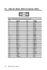
Page 24: ...SD 1 28 GND 4 SD 1 29 GND 5 SD 2 30 GND 6 SD 2 31 SATN 7 SD 3 32 SATN 8 SD 3 33 GND 9 SD 4 34 GND 10 SD 4 35 SBSY 11 SD 5 36 SBSY 12 SD 5 37 SACK 13 SD 6 38 SACK 14 SD 6 39 SRST 15 SD 7 40 SRST 16 SD...

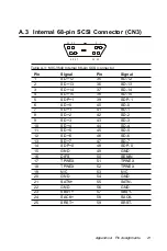
Page 25: ...4 37 SD 14 4 SD 15 38 SD 15 5 SDP 1 39 SDP 1 6 SD 0 40 SD 0 7 SD 1 41 SD 1 8 SD 2 42 SD 2 9 SD 3 43 SD 3 10 SD 4 44 SD 4 11 SD 5 45 SD 5 12 SD 6 46 SD 6 13 SD 7 47 SD 7 14 SDP 0 48 SDP 0 15 GND 49 GND...

Page 26: ...2 0 MIC 3640 User s Manual 26 SMSG 60 SMSG 27 SSEL 61 SSEL 28 SCD 62 SCD 29 SREQ 63 SREQ 30 SIO 64 SIO 31 SD 8 65 SD 8 32 SD 9 66 SD 9 33 SD 10 67 SD 10 34 SD 11 68 SD 11...

Page 27: ...4 37 SD 14 4 SD 15 38 SD 15 5 SDP 1 39 SDP 1 6 SD 0 40 SD 0 7 SD 1 41 SD 1 8 SD 2 42 SD 2 9 SD 3 43 SD 3 10 SD 4 44 SD 4 11 SD 5 45 SD 5 12 SD 6 46 SD 6 13 SD 7 47 SD 7 14 SDP 0 48 SDP 0 15 GND 49 GND...

Page 28: ...2 2 MIC 3640 User s Manual 26 SMSG 60 SMSG 27 SSEL 61 SSEL 28 SCD 62 SCD 29 SREQ 63 SREQ 30 SIO 64 SIO 31 SD 8 65 SD 8 32 SD 9 66 SD 9 33 SD 10 67 SD 10 34 SD 11 68 SD 11...

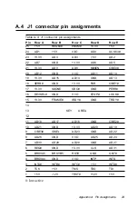
Page 29: ...ND V I O AD11 AD10 19 3 3V AD15 AD14 GND AD13 18 SERR GND 3 3V PAR C BE1 17 3 3V SDONE SBO GND PERR 16 DEVSEL GND V I O STOP LOCK 15 3 3V FRAME IRDY GND TRDY 14 13 KEY AREA 12 11 AD18 AD17 AD16 GND C...

Reviews: