


1 8
MIC-3385 User's Manual
2.1 IDE Device
The MIC-3385 provides two IDE (Integrated Device Electronics)
channels via the J3 connector to the rear transition board MIC-
3302. Four IDE drives can be connected to the MIC-3385 through
the rear transition board MIC-3302.
Users can connect two IDE drives to each IDE channel. If two
drives are installed on one channel, remember to set one as the
master and the other one as the slave. You may do this by setting
the jumpers on the drives. Refer to the documentation that came
with your drive for more information. A jumper diagram usually
appears on the top side of a hard disk drive.
Warning:
Plug the other end of the cable into the drive with
pin 1 on the cable corresponding to pin 1 on the
drive. Improper connection will damage the drive.
2.2 Floppy Drive
The MIC-3385 supports two floppy disk drives via the J3
connector to the rear transition board MIC-3302. Users can
connect up to two floppy drives to the connector on the MIC-
3302.
2.3 VGA Display Connector (CN2)
The MIC-3385 provides an VGA chipset built-in display for high
performance application. The MIC-3385's CN2 is a DB-15
connector for VGA monitor input. Pin assignments for the VGA
display are detailed in Appendix B.
Summary of Contents for MIC-3385
Page 9: ...Hardware Configuration C H A P T E R 1...
Page 24: ...16 MIC 3385 User s Manual...
Page 25: ...C H A P T E R 2 Connecting Peripherals...
Page 31: ...C H A P T E R 3 Ethernet Software Configuration...
Page 40: ...32 MIC 3385 User s Manual 16 Click Next 15 Click Next...
Page 42: ...34 MIC 3385 User s Manual...
Page 43: ...C H A P T E R 4 AGP VGA Setup...
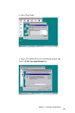
Page 47: ...Chapter 4 AGP VGA Setup 39 6 Click Setup exe 5 Click M3WinNT...
Page 48: ...40 MIC 3385 User s Manual 8 Click Yes 7 Click Next...
Page 50: ...42 MIC 3385 User s Manual...
Page 51: ...C H A P T E R 5 Award BIOS Setup...
Page 64: ...56 MIC 3385 User s Manual...
Page 65: ...Programming the Watchdog Timer A P P E N D I X A...
Page 68: ...60 MIC 3385 User s Manual...