Advantech IPC-631 User Manual Download Page 3

iii

IPC-631 User Manual

/ 用户手册


On-line Technical Support

/ 在线技术支持 / 線上技術支援

For technical support and service, please visit our support website at:
http://support.advantech.com

如需技术支持和服务,请访问研华公司的网站:

http://support.advantech.com.cn

若需技術支援及其它服務,請連結研華公司的支援網站:

http://support.advantech.com.tw

Instructions/

安全指示

1.

Read these safety instructions carefully.

2.

Keep this User Manual for later reference.

3.

Disconnect this equipment from any AC outlet before cleaning. Use a damp 
cloth. Do not use liquid or spray detergents for cleaning.

4.

For plug-in equipment, the power outlet socket must be located near the equip-
ment and must be easily accessible.

5.

Keep this equipment away from humidity.

6.

Put this equipment on a reliable surface during installation. Dropping it or letting 
it fall may cause damage.

7.

Do not leave this equipment in an environment unconditioned where the storage 
temperature under 0

° 

C (32

° 

F) or above 40

° 

C (104

° 

F), it may damage the 

equipment.

8.

The openings on the enclosure are for air convection. Protect the equipment 
from overheating. DO NOT COVER THE OPENINGS.

9.

Make sure the voltage of the power source is correct before connecting the 
equipment to the power outlet.

10.

Position the power cord so that people cannot step on it. Do not place anything 
over the power cord.

11.

All cautions and warnings on the equipment should be noted.

12.

If the equipment is not used for a long time, disconnect it from the power source 
to avoid damage by transient overvoltage.

13.

Never pour any liquid into an opening. This may cause fire or electrical shock.

14.

Never open the equipment. For safety reasons, the equipment should be 
opened only by qualified service personnel.

15.

If one of the following situations arises, get the equipment checked by service 
personnel:



The power cord or plug is damaged.



Liquid has penetrated into the equipment.



The equipment has been exposed to moisture.



The equipment does not work well, or you cannot get it to work according to 

the user's manual.



The equipment has been dropped and damaged.



The equipment has obvious signs of breakage.

16.

CAUTION: 

The computer is provided with a battery-powered real-time clock cir-

cuit. There is a danger of explosion if battery is incorrectly replaced. Replace 

Summary of Contents for IPC-631

Page 1: ...User Manual IPC 631 Compact 4U Front I O Rackmount Chassis for ATX MicroATX Motherboard ATX MicroATX 4U I O ATX MicroATX 4U IO...

Page 2: ...ed in any form or by any means without the prior written permission of Advantech Co Ltd Information provided in this manual is intended to be accurate and reliable How ever Advantech Co Ltd assumes no...

Page 3: ...COVER THE OPENINGS 9 Make sure the voltage of the power source is correct before connecting the equipment to the power outlet 10 Position the power cord so that people cannot step on it Do not place...

Page 4: ...ions while the power is on Sensitive electronic components can be damaged by sudden power surges 20 CAUTION Always ground yourself to remove any static charge before touching the motherboard backplane...

Page 5: ...v IPC 631 User Manual 16 17 CD IEC 60825 18 FCC 15 1 2 19 20 21 22 CCC 23 1 2 3 4 5 6 7 0 C 32 F 40 C 104 F 8 9 10 11 12 13 14 15 CLASS I LASER PRODUCT KLASS I LASER PRODUKT...

Page 6: ...s trial environments Whether your new Advantech equipment is destined for the labo ratory or the factory floor you can be assured that your product will provide the reliability and ease of operation f...

Page 7: ...pplication requirements or spe cific information on the installation and operation of any of our products Product Warranty Advantech warrants to you the original purchaser that each of its products wi...

Page 8: ...s defective obtain an RMA return merchandise authorization number from your dealer This allows us to process your return more quickly 4 Carefully pack the defective product a fully completed Repair an...

Page 9: ...ntative immediately We have carefully inspected the product mechanically and electrically before shipment It should be free of marks and scratches and in perfect working order upon receipt As you unpa...

Page 10: ...with a battery powered real time clock circuit There is a danger of explosion if battery is incorrectly replaced Replace only with same or equivalent type recommended by the manufacture Discard used...

Page 11: ...r cushions and hold down clamp 7 2 4 Installing Disk Drives 8 2 4 1 Installing HDD or Slim type Optical Disk Drive 8 Figure 2 4 Installing Slim ODD internal dual 2 5 HDD 2 5 2 5 8 Figure 2 5 Installin...

Page 12: ...aces 14 3 2 1 LED indicators for System Status 14 Table 3 1 LED Indicator functions 14 3 3 The Rear Panel 15 Figure 3 2 Rear panel for motherboard version 15 3 4 Replacing the Cooling Fan 15 3 5 Clean...

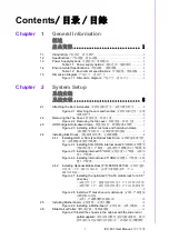
Page 13: ...Chapter 1 1 General Information...

Page 14: ...W high efficiency power supply IPC 631 I O 4U IPC 631 350 mm ATX micro ATX 7 PWM MB IPC 631 1 1 3 5 1 3 5 2 2 5 2 2 5 500 W IPC 631 I O 4U IPC 631 350mm ATX micro ATX 7 PWM MB IPC 631 1 1 3 5 1 3 5 2...

Page 15: ...ns Model PS8 500ATX ZE RPS8 500ATX ZE Watt 500 W ATX PFC 500 W ATX PFC 80 Plus Grade Bronze Gold Input rating 90 264 Vac 90 264 Vac PSU Type PS 2 Rudundant PSU Output voltage 3 3V 24 A 5 V 20 A 12 V1...

Page 16: ...ronment Operating Non operating Temperature 0 40 C 32 104 F 40 70 C 40 158 F Humidity 10 85 40 C non condensing 10 95 60 C non condensing Vibration 5 500Hz 1G rms 2 G Shock 10 G with 11 ms duration ha...

Page 17: ...Chapter 2 2 System Setup...

Page 18: ...taching the ears and handles Note Use caution when installing or operating the components with the chas sis open Be sure to turn off the power unplug the power cord and ground yourself by touching the...

Page 19: ...7 IPC 631 User Manual Chapter 2 System Setup 2 2 Removing the Top Cover Figure 2 2 Removing the top cover 2 3 HDD bridge Hold down Clamp Figure 2 3 Installing rubber cushions and hold down clamp...

Page 20: ...1 User Manual 8 2 4 Installing Disk Drives 2 4 1 Installing HDD or Slim type Optical Disk Drive Figure 2 4 Installing Slim ODD internal dual 2 5 HDD 2 5 2 5 Figure 2 5 Installing internal 3 5 HDD 3 5...

Page 21: ...N 98R1310010E P N 98R1310010E P N 98R1310010E Users may purchase an optional mobile rack P N 98R1310010E to covert a 3 5 drive bay to dual 2 5 SATA HDD trays P N 98R1310010E 1 3 5 2 2 5 SATA HDD P N 9...

Page 22: ...IPC 631 User Manual 10 Figure 2 8 Install a 2 5 disk drive on mobile rack 2 5 2 5 2 5 Installing Motherboard Figure 2 9 Installing a Motherboard...

Page 23: ...User Manual Chapter 2 System Setup 2 6 Slide Rail or Pallet Figure 2 10 Install the chassis in the cabinet with the slide rail or pallet supplied 2 7 Power cord hook Figure 2 11 Power cord hook insta...

Page 24: ...IPC 631 User Manual 12...

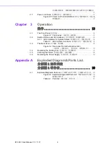
Page 25: ...Chapter 3 3 Operation...

Page 26: ...er on or off Please use system shutdown or press this switch for few seconds to turn off the sys tem ATX power System Reset button Press this button to reboot the system ATX ATX 3 2 1 LED indicators f...

Page 27: ...631 User Manual Chapter 3 Operation 3 3 The Rear Panel Figure 3 2 Rear panel for motherboard version 3 4 Replacing the Cooling Fan Figure 3 3 Replacing the system cooling fan without removing the top...

Page 28: ...IPC 631 User Manual 16 3 5 Cleaning the Filters Figure 3 4 Removing the Filters 3 6 Replacing the Power Supply Figure 3 5 Replacing the single power supply...

Page 29: ...17 IPC 631 User Manual Chapter 3 Operation Figure 3 6 Replacing the redundant power supply Figure 3 7 Power cord plugs should have same orientation in the socket...

Page 30: ...IPC 631 User Manual 18...

Page 31: ...Appendix A A Exploded Diagram Parts List...

Page 32: ...IPC 631 User Manual 20 A 1 Exploded Diagram Parts List Figure A 1 Exploded Diagrams Parts List 13 14 1 2 3 4 5 6 7 8 9 10 11 12 12 13 15 14 15 16 17 18 19 20...

Page 33: ...PS 2 PS 2 2 RESET SWITCH BRACKET 12 EAR 3 HDD COVER 13 HANDLE 4 SLIM ODD COVER 14 FAN GUARD 5 PS 2 POWER BRACKET PS 2 PS 2 15 12CM SYSTEM FAN 12 12 6 POWER SWITCH 16 CHASSIS 7 PHOENIX CONNECTOR 17 DRI...

Page 34: ...e No part of this publication may be reproduced in any form or by any means electronic photocopying recording or otherwise without prior written permis sion of the publisher All brand and product name...

Reviews: