background image

IDS-3115 User Manual

20

3.4

Mounting Notes (for Projected Capacitive 

Touchscreen)

Projected Capacitive touchscreens detect the touch location by measuring the
increased amount of the capacitance value between its electrodes at inputs. Once it
is built into a system, capacitance couplings are continually yielded among the touch-
screen. When turned on, our projected capacitive touchscreen will automatically
adjust its sensitivity level to the surrounding environment in standby state in order to
avoid the affects by the surrounding capacitance couplings. If the surrounding envi-
ronment changes or the device is near materials that alter the electrical field (a large
capacitor, power-supply unit, LCD panel, or materials with high dielectric constant),
these external factors will adversely affect the function of the touchscreen to detect
the correct input positions. 
Please refer to the mounting notes below and ensure enough gap among each com-
ponent in order to avoid trouble from the external factors described above. 
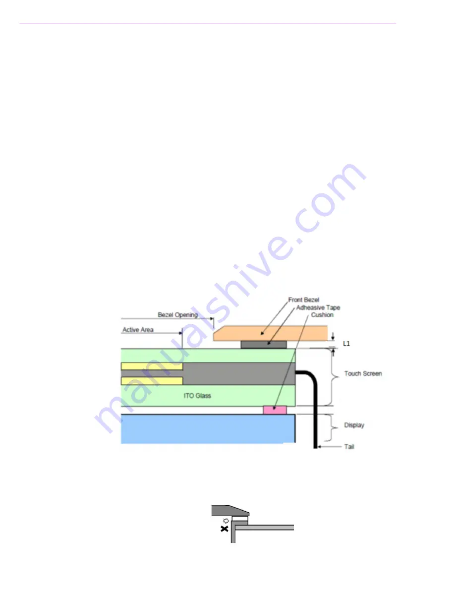
3.4.1

Mounting Touchscreen on Back Side of the Bezel

Fix the touchscreen firmly so that the gap distances between the touchscreen and
other components will not be affected by touching or will not change with the passage
of time. An unexpected input may be caused if the gap is too narrow. 
It is recommended to use an insulating resin material for the bezel. If a metal plate is
used for the bezel, unintended capacitance coupling may occur on the periphery of
the active area. 
If a metal plate or any other metallic materials is used for the bezel, ensure a gap dis-
tance of approximately 2mm between the touchscreen and the bezel (L1)

3.4.2

Tail

The tail must not be forcibly stressed or bent too hard or it may cause conduction in
the insulated area and/or wire breaking..

Summary of Contents for IDS-3115 Series

Page 1: ...User Manual IDS 3115 Series 15 Industrial Open Frame Monitor...

Page 2: ...dvantech assumes no liability under the terms of this warranty as a consequence of such events Because of Advantech s high quality control standards and rigorous testing most of our customers never ne...

Page 3: ...is likely to cause harmful interference in which case the user will be required to correct the interference at his own expense FM This equipment has passed FM certification According to the National...

Page 4: ...ions are included to help you avoid damaging hardware or losing data e g There is a danger of a new battery exploding if it is incorrectly installed Do not attempt to recharge force open or heat the b...

Page 5: ...y reasons the equipment should be opened only by qualified service personnel 14 If one of the following situations arises get the equipment checked by service personnel The power cord or plug is damag...

Page 6: ...IDS 3115 User Manual vi...

Page 7: ...u 13 3 1 5 Color Temperature Submenu 14 3 1 6 Language Submenu 14 3 1 7 OSD Setting Submenu 14 3 1 8 VGA DVI Selection 15 3 2 OSD Functions for IDS 3115E Series 15 3 2 1 OSD Main Menu Push the MENU Ke...

Page 8: ...IDS 3115 User Manual viii...

Page 9: ...Chapter 1 1 Overview Sections include Introduction Features Applications Product Photos Naming Convention...

Page 10: ...A LED backlight panel which provides 20 30 power saving 20 C 60 C wide operating temperature range support Special design of 5 wire resistive and optional P cap dual touch is supported touchscreen All...

Page 11: ...3 IDS 3115 User Manual Chapter 1 Overview Rear view IDS 3115 Bottom view IDS 3115E Bottom View 1 5 Naming Convention IDS 3 1 15 W R 40 XG A1E Uzqf Revision...

Page 12: ...IDS 3115 User Manual 4...

Page 13: ...Chapter 2 2 System Setup Sections include Specifications Dimensions Rear Mount Assembly SOP Cable Clamp Accessory Packing...

Page 14: ...0 60 C 4 140 F 20 60 C 4 140 F 0 45 C 32 113 F Storage Temperature 30 70 C 22 158 F 30 70 C 22 158 F 20 60 C 4 140 F Humidity 5 95 40 C non condensing Vibration 5 500Hz 0 026G Hz 2 16Grms X Y Z 1 hour...

Page 15: ...7 IDS 3115 User Manual Chapter 2 System Setup 2 2 Dimensions Figure 2 1 IDS 3115 High Brightness Series Dimensions Figure 2 2 IDS 3115 Series Dimensions Figure 2 3 IDS 3115E Series Dimensions...

Page 16: ...Mount Assembly SOP 1 Using the M3 screws 12 pcs included attach and tighten as shown in the below figure 2 4 Cable Clamp 1 A cable clamp also comes with IDS 3115 to affix the power cable to the back o...

Page 17: ...1 8 meter 1 x USB A M USB A M 1 8 meter 8 x panel mount clamps 8 x Panel mount clamper screws M4_25L 1 x cable clamp 1 x cable clamp screw 1 x cable tie 1 x 60 W DC12V Power Adapter optional 1 x Powe...

Page 18: ...IDS 3115 User Manual 10...

Page 19: ...Chapter 3 3 Touchscreen Sections include OSD Functions Touch Drivers Mounting Notes for P cap...

Page 20: ...3 1 1 OSD Main Menu Push the MENU Key Buttons Description Power Turn the monitor power ON or OFF Menu Activate the OSD menu Exit menu Auto Automatically adjust the clock phase H position and V positio...

Page 21: ...13 IDS 3115 User Manual Chapter 3 Touchscreen 3 1 2 Brightness Selection Submenu 3 1 3 Contrast Control 3 1 4 Screen Settings Submenu...

Page 22: ...IDS 3115 User Manual 14 3 1 5 Color Temperature Submenu 3 1 6 Language Submenu 3 1 7 OSD Setting Submenu...

Page 23: ...ser Manual Chapter 3 Touchscreen 3 1 8 VGA DVI Selection 3 2 OSD Functions for IDS 3115E Series 3 2 1 OSD Main Menu Push the MENU Key 3 2 2 OSD Lock Press the Right and Menu keys simultaneously to loc...

Page 24: ...IDS 3115 User Manual 16 3 2 3 OSD Unlock Press the Right and Menu keys simultaneously again to unlock the OSD key 3 2 4 Color Adjustment Submenu Brightness Contrast Color Adjust Color temp Auto Color...

Page 25: ...17 IDS 3115 User Manual Chapter 3 Touchscreen 3 2 5 Image Setting Adjustment 3 2 6 Image Adjustment Submenu Clock Phase H Position V Position...

Page 26: ...IDS 3115 User Manual 18 3 2 7 OSD Menu Adjustment 3 2 8 OSD Adjustment Submenu OSD H Pos OSD V Pos OSD Timer...

Page 27: ...al Chapter 3 Touchscreen 3 2 9 OSD Adjustment Language Submenu 3 2 10 Reset Adjustment 3 3 Touch Drivers The touchscreen driver is available online at the Advantech website http support advantech com...

Page 28: ...the function of the touchscreen to detect the correct input positions Please refer to the mounting notes below and ensure enough gap among each com ponent in order to avoid trouble from the external...

Page 29: ...Appendix A A Troubleshooting...

Page 30: ...The image is incorrectly displayed or the full screen image does not appear Please make sure the screen resolution on the motherboard is correct The position of screen is not in the center Adjust the...

Page 31: ...23 IDS 3115 User Manual Appendix A Troubleshooting...

Page 32: ...tions are subject to change without notice No part of this publication may be reproduced in any form or by any means electronic photocopying recording or otherwise without prior written permis sion of...

Reviews: