


9
HPC-2040 User Manual /
用户手册
Chapter 2
S
ystem
Setup
系统安装 系統安裝
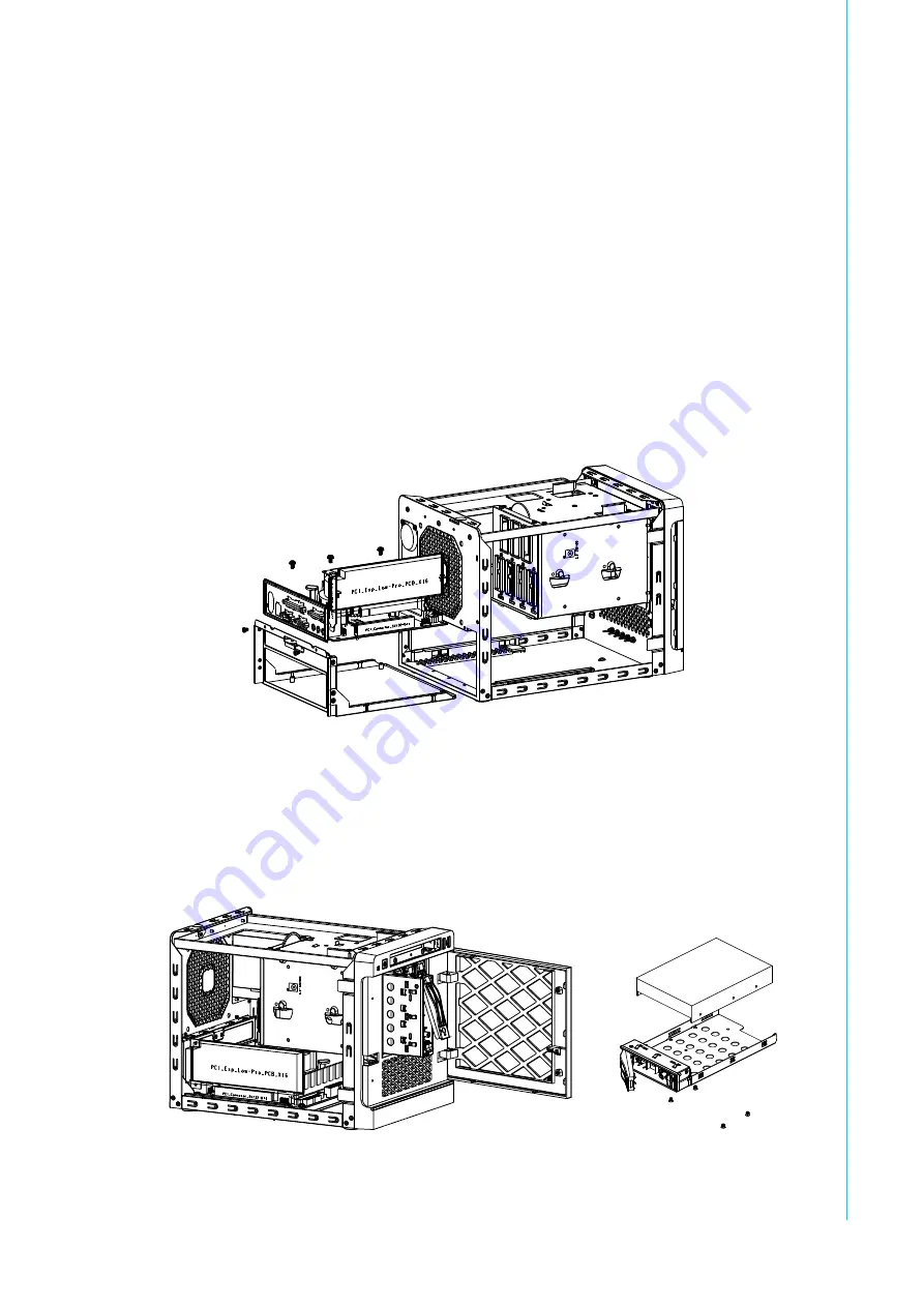
2.2
Installing Motherboard and Low-profile
Expansion card
/ 安装主板以及扩展卡 / 安裝主機板
以及擴充卡
1.
Release two screws, then press the clip and pull the motherboard tray.
移除抽取盒后方两颗螺丝后 , 将收取盒卡楯下压后拉出抽取盒
移除抽取盒後方兩顆螺絲後 , 將收取盒卡楯下壓後拉出抽取盒
2.
Release one screw and remove the expansion card bracket.
将主板安装并锁附在抽取盒内
將主機板安裝並鎖附在抽取盒內
3.
Release one screw and remove the expansion card bracket.
移除扩充卡档板之螺丝并移除档板后装入扩充卡
移除擴充卡檔板之螺絲並移除檔板後裝入擴充卡
Figure 2.2 Installing Motherboard
/ 安装母板 / 安裝主機板
2.3
Installing Disk Drives
/ 安装磁盘驱动器 / 安裝磁碟機
2.3.1
Installing 3.5" HDD
/ 安装 3.5" 硬盘 / 安裝 3.5" 硬碟
Figure 2.3 Installing 3.5" HDD /
安装 3.5" 硬盘 / 安裝 3.5" 硬碟
Summary of Contents for HPC-2040
Page 1: ...User Manual HPC 2040 Mini Tower Server Chassis for Mini ITX Motherboard Mini ITX Mini ITX...
Page 10: ...HPC 2040 User Manual x...
Page 12: ...HPC 2040 User Manual xii Figure A 1 Exploded Diagrams Parts List 16 Table A 1 Parts list 16...
Page 13: ...Chapter 1 1 General Information...
Page 18: ...HPC 2040 User Manual 6...
Page 19: ...Chapter 2 2 System Setup...
Page 23: ...Chapter 3 3 Operation...
Page 27: ...Appendix A A Exploded Diagram Parts List...
Page 29: ...17 HPC 2040 User Manual Appendix A Exploded Diagram Parts List...


