background image

25

Appendix A  

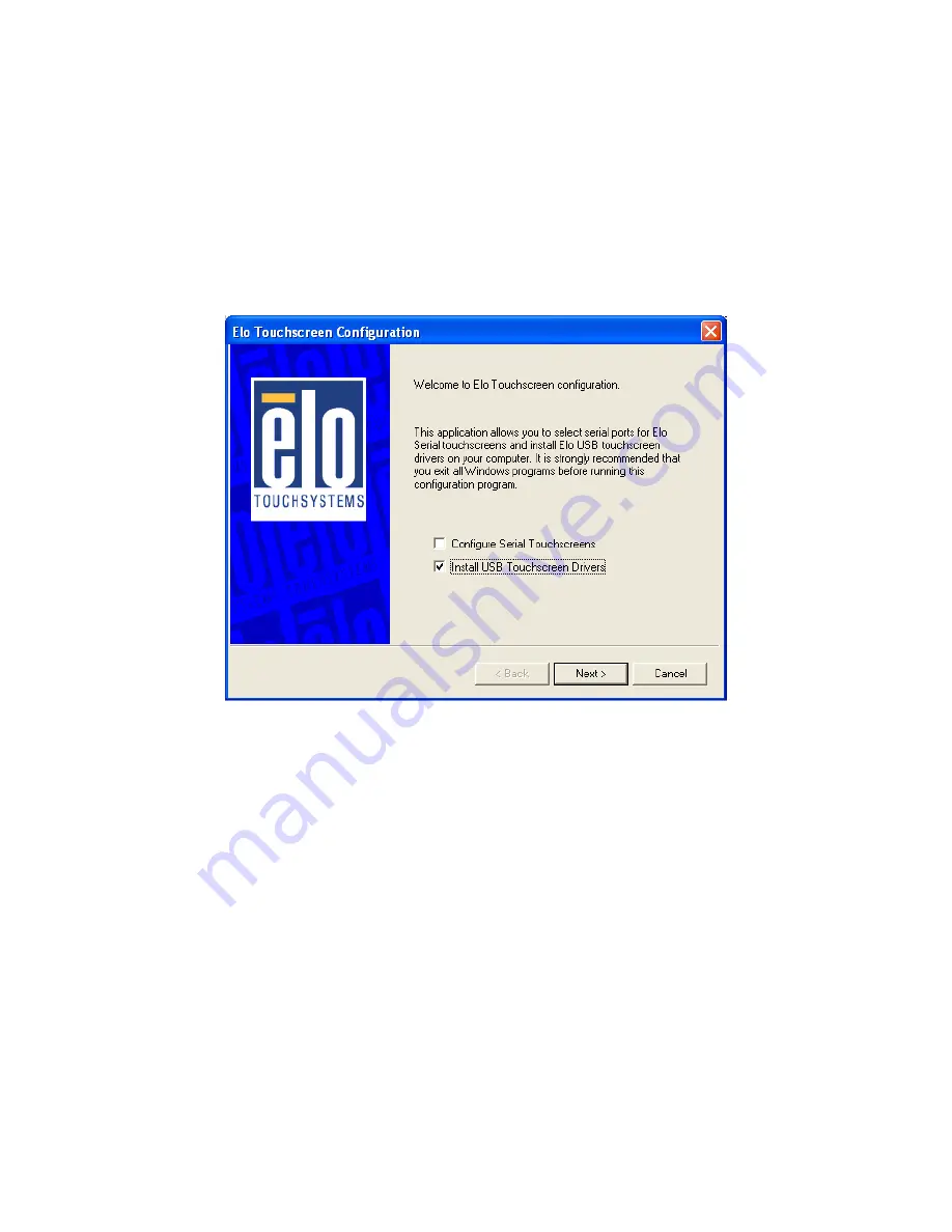
•  Adding Additional USB Controllers
If there are Elo USB devices already installed, plug the USB cable from 
the touchmonitor into the computer and run EloVA to calibrate the touch-
monitors.
 If there are no Elo USB devices attached to the system, click on the 
Change option from the Add/Remove programs in the Control Panel, Elo 
entry.

Summary of Contents for FPM-3190G Series

Page 1: ...i FPM 3190G Industrial Flat Panel Monitor with 19 TFT LCD Display User Manual ...

Page 2: ...vided in this manual is intended to be accurate and reliable However Advantech Co Ltd assumes no responsibility for its use nor for any infringements upon the rights of third parties which may result from its use All brand and product names mentioned herein are trademarks or regis tered trademarks of their respective holders This Manual Covers the Following Models FPM 3190G XBE Industrial 19 SXGA ...

Page 3: ...lacement materials service time and freight Please consult your dealer for more details If you think you have a defective product follow these steps 1 Collect all the information about the problem encountered For example CPU speed Advantech products used other hardware and software used etc Note anything abnormal and list any onscreen messages you get when the problem occurs 2 Call your dealer and...

Page 4: ... equipment on and off If the interference is occurring the user is encouraged to try to correct the interference by one or more of the following measures Reorient or relocate the receiving antenna Increase the separation between the equipment and the receiver Connect the equipment to a power outlet on a circuit different from that to which the receiver is connected Consult the dealer or an experie...

Page 5: ... not used for a long time disconnect it from the power source to avoid damage by transient overvoltage 12 Never pour any liquid into an opening This may cause fire or electrical shock 13 Never open the equipment For safety reasons the equipment should be opened only by qualified service personnel 14 If one of the following situations arises get the equipment checked by service personnel a The powe...

Page 6: ...FPM 3190G User Manual vi ...

Page 7: ...top Stand for the FPM 3190G series 11 2 2 2 Swing ARM 12 Figure 2 5 Swing ARM for the FPM 3190G series 12 Appendix A Touchscreen Installation 14 A 1 Introduction 14 A 1 1 Resistive Type 14 A 1 2 Capacitive Type 15 A 2 Resistive Touchscreen Driver Installation 17 A 2 1 Hardware 17 A 2 2 Software 18 Appendix B Supported Input Timing Modes 28 B 1 Supported Input Timing Modes 28 Appendix C OSD Operati...

Page 8: ... User Manual viii C 2 6 RGB Color Menu 37 C 2 7 Language Menu 38 C 2 8 OSD Manager 39 C 2 9 Auto Configuration Menu 40 C 2 10 Mode Information Menu 41 C 2 11 Memory Recall Menu 42 C 2 12 Exit Menu 43 C 2 13 Hot Keys 44 ...

Page 9: ...CHAPTER 1 Introduction This chapter includes Introduction Specifications LCD Specification Connectors Dimensions ...

Page 10: ... CVBS connectors With the FPM 3190G Advantech is taking a more aggressive initiative to penetrate the industrial HMI market Its OSD On Screen Display function allows you to adjust the display factors and turn the backlight on and off for the front view functions which become criti cal as more and more industrial HMI users become aware of the benefits of flat panel monitors The whole chassis is of ...

Page 11: ...00 Hz 1 0 Grms Dimensions W x H x D 482 x 399 x 66 mm 19 x 15 7 x 2 6 Weight 10 65kg 23 46 lb Certifications CE FCC BSMI CCC certified Touchscreen Optional Type resistive sensor Resolution 4096 4096 for resistive model Light transmission 78 resistive 88 Operating Pressure 30 45 gram for stylus contact bounce 10 ms Controller RS 232 for R or C model or USB for U model Power Consumption 5 V 260 mA O...

Page 12: ...st Ratio 1000 1 1 4 Connectors The following connectors are situated on the left hand side of the FPM 3190 Series VGA Port DB 15 This DB 15 connector can be connected to the system via the external 15 pin DB 15 connector thru the I O from this unit DVI Connected with a standard DVI connector thru I O port of this unit Only supports digital signals S Video Connected with a standard S Video connecto...

Page 13: ...included with all orders which include the RS 232 touchscreen option Touchscreen Connector USB Optional This connector will be present only if a touchscreen is installed It must be connected to the USB port of the PC The touchscreen cable is included with all orders which include the USB touchscreen option DC 12V Power in This connector will be connected to a DC 12V Switching Power Supply ...

Page 14: ...FPM 3190G User Manual 6 1 5 Dimensions Figure 1 1 FPM 3190G Cutout Dimensions 444 x 376 mm 17 48 x 14 84 ...

Page 15: ...CHAPTER 2 System Setup This chapter includes Mounting the Monitor Wall Panel Rack Mounting Desktop Stand Swing ARM Mounting ...

Page 16: ...satility of the FPM 3190G mounts enable it to be mounted on your desk or any where else 2 1 1 Wall Mounting With wall brackets the FPM 3190G can be mounted directly to a wall If you need to install the FPM 3190G in different ways release the mounting brackets by detaching the four screws on the rear side Figure 2 1 Wall Mounting ...

Page 17: ... you need to install the FPM 3190G series on a panel mount please release the mounting brackets by detaching four screws on rear side and fix them on up and bottom side by screws Figure 2 2 Panel Mounting Cutout Dimensions 444 x 376 mm ...

Page 18: ... 3190G User Manual 10 2 1 3 Rack Mounting FPM 3190G series products could be directly mount to the industrial standard 19 rack There are four screw holes on each side of the panel Figure 2 3 Rack Mounting ...

Page 19: ...racket 2 2 1 Desktop Stand The desktop stand brackets are attached to the rear of FPM 3190G First loosen the screw in point C Then unscrew the screw in point A Pull down the bracket and use the screw from point A to fasten the bracket in point B There should be no screws in point A and point D Only point B and C Figure 2 4 Desktop Stand for the FPM 3190G series A B C D ...

Page 20: ... User Manual 12 2 2 2 Swing ARM Detach the mounting brackets on the rear side then attach the FPM 3190G series onto the Swing ARM mount 75mm or 100mm square bracket Figure 2 5 Swing ARM for the FPM 3190G series ...

Page 21: ...Appendix A Touchscreen Driver Installation ...

Page 22: ... Resistive Type Supply Voltage and Current 5 Vdc nominal 4 50 Vdc to 5 25 Vdc Self powered only 50 mA standby typical at 5 Vdc during touch 160 mA average 240 mA peak Average power dissipation is 0 5 W typical Supply must be capable of sourcing 400 mA minimum Total noise and ripple requirement must be less than 100 mV p p for frequencies below 1 MHz and less than 50 mV p p for frequen cies above 1...

Page 23: ...SmartSet command Initial Stream Untouch Z axis Enable Modes Touch Resolution 4096x4096 size independent Conversion Time Approximately 10 ms per coordinate set A 1 2 Capacitive Type Electrical Input Method Finger TouchPen available with qualified sensor attachments and electronics Accuracy and Precision Area Reported touch coordinates are within 1 0 of true position based on viewing area dimensions...

Page 24: ... similar non abrasive cleaners Reliability Endurance Test A capacitive sensor with Industrial etch has been tested in a laboratory environment to withstand over 225 million mechancial touches without noticable degradation to the surface Surface Obstructions Touch screen s operation unaffected by sur face obstructions such as dirt dust grease smoke peanut butter etc Chemical Resistance Capacitive s...

Page 25: ...ble Controller information will not be registered in the Property Page of the Control Panel USB USB controllers require no configuration prior to installation Elo s USB controllers are Human Interface Device HID compliant The Windows 2000 and Windows XP operating systems have native HID drivers that provide low level support for Elo touchscreen control lers An Elo touchmonitor with a USB touchscre...

Page 26: ... covered in this section Setup from Windows Desktop For WinXP OS please execute CDROM TouchScreen DRV ELOTOUCH WinXP SetupElo exe For Win2000 OS please execute CDROM TouchScreen DRV ELOTOUCH Win2K SetupElo exe Single monitor serial controller 1 Run the self extracting zip file to unzip the files using the Run EloSetup option 2 EloSetup will launch Check the Install Serial Touchscreen Driv ers box ...

Page 27: ... click Next and proceed to the next screen 6 The COM port you selected will be shown in the window of this screen This is your last opportunity to change your COM port selection before the driver files are installed Use the Back but ton s to change any of the selections you previously made Click Next to complete the installation of the driver files 7 Depending on the revision of the driver you are...

Page 28: ... USB controller 1 Run the self extracting zip file to unzip the files using the Run EloSetup option 2 EloSetup will launch Check the Install USB Touchscreen Driv ers box 3 Review and accept the License Agreement 4 The driver files will install When the Setup Complete screen appears you may choose to run calibration the Elo Video Align ment program EloVA immediately or wait until later If you choos...

Page 29: ...bration for any monitor or allow the program to time out as indicated by the progress bar reaching maximum Multiple monitors USB controllers 1 Follow the procedure for Single monitor USB controller installa tion above 2 The driver files will install When the Setup Complete screen appears you may choose to run calibration the Elo Video Align ment program EloVA immediately or wait until later If you...

Page 30: ...e not to run this program now you can run it from the Elo Control Panel application When EloVA runs for the first time it will attempt to calibrate all controllers and or serial ports that were installed Press the Esc key on the keyboard to terminate or skip calibration for any monitor or allow the program to time out as indicated by the progress bar reaching maximum The program will continue unti...

Page 31: ...23 AppendixA Adding Additional Serial Controllers Click on the Change option from the Add Remove programs in the Con trol Panel Elo entry ...

Page 32: ...FPM 3190G User Manual 24 Change Serial Port To change Serial port click on the Change option from the Add Remove programs in the Control Panel Elo entry ...

Page 33: ...evices already installed plug the USB cable from the touchmonitor into the computer and run EloVA to calibrate the touch monitors If there are no Elo USB devices attached to the system click on the Change option from the Add Remove programs in the Control Panel Elo entry ...

Page 34: ...FPM 3190G User Manual 26 ...

Page 35: ...Appendix B Supported Input Timing Modes ...

Page 36: ...lues are memorized in every preset number Note 2 This module recognizes the synchronous signals with near preset timing of the frequency of the HS and Vsync even in the case that the signals other than the preset timing that were entered Note 3 Because adjustments may not fit such as differing magnifying ratios or in the case that you use it except for the display timing that was preset Table B 1 ...

Page 37: ...Appendix C OSD Operation Keypad ...

Page 38: ...to Exit Automatically adjust the clock phase H position and V position Exit menu Down Right Increase Activate the volume control Move the selector to the next option Increase the gauge value of the selected option Up Left Decrease Active volume control Move the selector to the previous option Decrease the gauge value of the selected option Menu Sel Activate the OSD menu Enter confirm the selected ...

Page 39: ...e in case a selected mode is changed before time out or power is turned off before time out TIME OUT Æ 5 6 seconds Can be set in OSD Manager The default definition of input keys is shown as following C 2 1 Menu Start Generate Main Menu Press MENU Button in OSD function key Main Menu DISPLAY IN SCREEN Sub Menu DISPLAY IN SCREEN N A Available Key Functions N A N A Select to exit menu or wait for tim...

Page 40: ...Button press Menu Button for selection confirmation Main Menu DISPLAY IN SCREEN Sub Menu DISPLAY IN SCREEN Available Key Functions Power Off the LCD Monitor Increase the gauge value of the selected option Return to last menu Selected to confirm Decrease the gauge value of the selected option N A ...

Page 41: ...wing sequence from ANALOG INPUT DIGITAL INPUT S VIDEO INPUT and CVBS INPUT OFF Æ start from default setting C 2 3 Contrast Brightness Setting Generate Main Menu Select by Left and Right Button press Menu Button for selection confirmation Main Menu DISPLAY IN SCREEN n Sub Menu DISPLAY IN SCREEN ...

Page 42: ...nt screen setting Recall Æ Switch the setting change by Rec1 and Rec2 while pressed C 2 4 Geometry Menu For DVI Input Generate Main Menu Select by Left and Right Button press Menu Button for selection confirmation Main Menu DISPLAY IN SCREEN Sub Menu DISPLAY IN SCREEN Power Off the LCD Monitor Increase the gauge value of the selected option Return to last menu Selected to confirm Decrease the gaug...

Page 43: ...35 AppendixC Available Key Functions Power Off the LCD Monitor Increase the gauge value of the selected option Return to last menu Selected to confirm Decrease the gauge value of the selected option N A ...

Page 44: ...t Button press Menu Button for selection confirmation Main Menu DISPLAY IN SCREEN Sub Menu DISPLAY IN SCREEN Available Key Functions Power Off the LCD Monitor Increase the gauge value of the selected option Return to last menu Selected to confirm Decrease the gauge value of the selected option N A ...

Page 45: ...Main Menu Select by Left and Right Button press Menu Button for selection confirmation Select by Left and Right Button Press Menu Button for selection confirmation Main Menu DISPLAY IN SCREEN Sub Menu DISPLAY IN SCREEN Sub Menu DISPLAY IN SCREEN ...

Page 46: ...rate Main Menu Select by Left and Right Button press Menu Button for selection confirmation Main Menu DISPLAY IN SCREEN Sub Menu DISPLAY IN SCREEN Power Off the LCD Monitor Increase the gauge value of the selected option Return to last menu Selected to confirm Decrease the gauge value of the selected option N A ...

Page 47: ...eft and Right Button press Menu Button for selection confirmation Main Menu DISPLAY IN SCREEN Sub Menu DISPLAY IN SCREEN Power Off the LCD Monitor Increase the gauge value of the selected option Return to last menu Selected to confirm Decrease the gauge value of the selected option N A ...

Page 48: ... Select by Left and Right Button press Menu Button for selection confirmation Main Menu DISPLAY IN SCREEN Sub Menu DISPLAY IN SCREEN Power Off the LCD Monitor Increase the gauge value of the selected option Return to last menu Selected to confirm Decrease the gauge value of the selected option N A ...

Page 49: ...de Information Menu Generate Main Menu Select by Left and Right Button press Menu Button for selection confirmation Main Menu DISPLAY IN SCREEN Sub Menu DISPLAY IN SCREEN Power Off the LCD Monitor Increase the gauge value of the selected option Return to last menu Selected to confirm Decrease the gauge value of the selected option N A ...

Page 50: ...elect by Left and Right Button press Menu Button for selection confirmation Main Menu DISPLAY IN SCREEN Sub Menu DISPLAY IN SCREEN Power Off the LCD Monitor Increase the gauge value of the selected option Return to last menu Selected to confirm Decrease the gauge value of the selected option N A ...

Page 51: ...eft and Right Button press Menu Button for selection confirmation Main Menu DISPLAY IN SCREEN Sub Menu DISPLAY IN SCREEN Power Off the LCD Monitor Increase the gauge value of the selected option Return to last menu Selected to confirm Decrease the gauge value of the selected option N A ...

Page 52: ...ton press so that you can have OSD LOCK and UNLOCK setting Entry OSD LOCK MODE Press HOT KEY the screen will show this action first Don t remove the HOT KEY until the screen indicated this task is fin ished Power Off the LCD Monitor Increase the gauge value of the selected option Return to last menu Selected to confirm Decrease the gauge value of the selected option N A ...

Page 53: ...45 AppendixC Entry OSD UNLOCK MODE Press HOT KEY the screen will show this action first Don t remove the HOT KEY until the screen indicated this task is fin ished ...

Page 54: ...FPM 3190G User Manual 46 ...

Reviews: