Administrator’s Guide and Operating Instructions
5
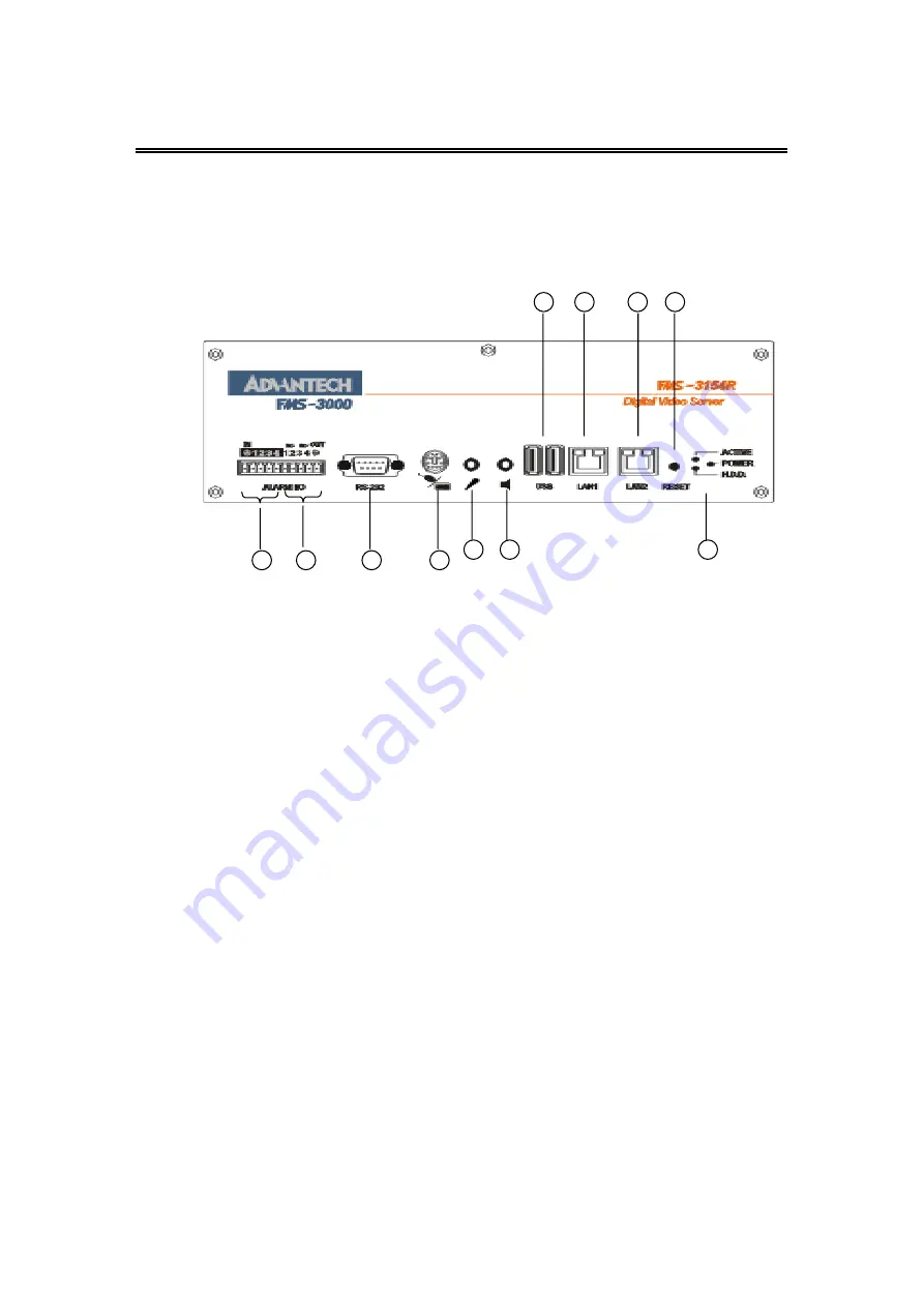
Front Panel
9. Alarm In 1-4: Connects to alarm inputs 1-4 & 1 common ground.
10. Alarm Out: Connects to 2 Normally Closed alarm outputs (1-2), 2
Normally Open alarm outputs (3-4) & 1 common ground.
11. RS232 connector #1: Connects to Modem.
12. Mouse (Y Cable) Connector: Connects to the PS2 mouse or the
Y cable (attached) for the mouse and keyboard (optional) connection.
The mouse must be connected at system startup
.
13. Audio In (reserved).
14. Audio Out (reserved).
15. 2 USB connectors: Connect to the DVD RAM, ZIP, printer, USB port
ISDN TA(Terminal Adapter) device or USB hub.
16. LAN connector 1: For peer-to-peer connection (reserved).
17. LAN connector 2: Connects to the RJ45 LAN connector.
18. Reset Button.
19. LEDs: LEDs for system active, power and HDD access.
9
10
11
12
13
14
15
16
17
18
19
Summary of Contents for FMS-3154R
Page 61: ...P N MDR4G00200 Jan 16 2002 ...


