background image

EKI-6538 User Manual

30

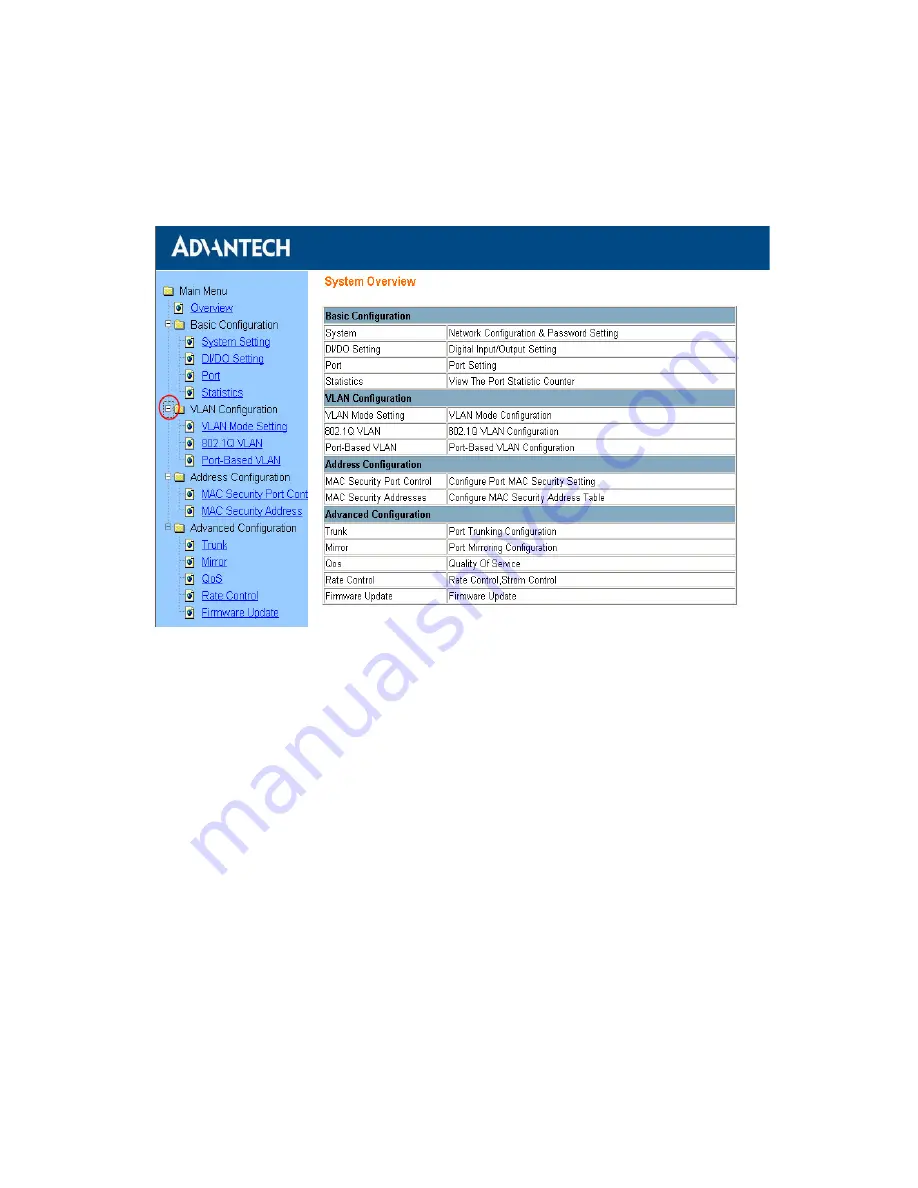
In the Overview page, you can find the overview and the brief description 
of the functions EKI-6538 provided. Click the “

+

” symbol to unroll the 

hiding hyperlink, and click the hyperlink to open the function page you 
want to configure.

Figure 3.10: Function Overview Page

3.2.1 Basic Configuration

System Settings

In this page, you can find the current firmware version and the MAC 
address of EKI-6538. You can also make configuration for the network, 
password and ARL aging time.  Remember to press the “Apply” button to 
save your configuration.

Warning

Don't set "0" for the first segment of the subnet 
mask and default gateway (000.xxx.xxx.xxx)
Refresh the web screen if the web could not be 
displayed while you change the setting. 

Summary of Contents for EKI-6538

Page 1: ...EKI 6538 8 port 10 100 Mbps Industrial Smart Ethernet Switch User Manual ...

Page 2: ...by any means without the prior written permission of Advantech Co Ltd Information provided in this manual is intended to be accurate and reli able However Advantech Co Ltd assumes no responsibility for its use nor for any infringements of the rights of third parties which may result from its use Acknowledgements Intel and Pentium are trademarks of Intel Corporation Microsoft Windows and MS DOS are...

Page 3: ...placement materials service time and freight Please consult your dealer for more details If you think you have a defective product follow these steps 1 Collect all the information about the problem encountered For example CPU speed Advantech products used other hardware and software used etc Note anything abnormal and list any onscreen messages you get when the problem occurs 2 Call your dealer an...

Page 4: ...ses and can radiate radio frequency energy and if not installed and used in accordance with the instruction manual may cause harmful interference to radio communications Opera tion of this equipment in a residential area is likely to cause harmful inter ference in which case the user will be required to correct the interference at his own expense Technical Support and Assistance Step 1 Visit the A...

Page 5: ...ipment to the power outlet 9 Position the power cord so that people cannot step on it Do not place anything over the power cord 10 All cautions and warnings on the equipment should be noted 11 If the equipment is not used for a long time disconnect it from the power source to avoid damage by transient overvoltage 12 Never pour any liquid into an opening This may cause fire or elec trical shock 13 ...

Page 6: ...atic Electricity Follow these simple precautions to protect yourself from harm and the products from damage 1 To avoid electrical shock always disconnect the power from your PC chassis before you work on it Don t touch any components on the CPU card or other cards while the PC is on 2 Disconnect power before making any configuration changes The sudden rush of power as you connect a jumper or insta...

Page 7: ... Figure 2 7 Installation to DIN Rail Step 1 16 Figure 2 8 Installation to DIN Rail Step 2 17 Figure 2 9 Installation to DIN Rail Step 3 18 2 5 Network Connection 18 2 6 Power Connection 19 Figure 2 10 Pin Assignment of the Power Connector 19 2 7 Digital Inputs Outputs 20 Figure 2 11 Digital I O Pin Assignment 20 Figure 2 12 Digital Output Connection 20 2 8 RS 232 Connection 21 Figure 2 13 RJ 48 10...

Page 8: ... Port 36 3 2 2 VLAN Configuration 36 Figure 3 18 VLAN Mode Setting 36 Figure 3 19 Default Port based VLAN Setting Screen 37 Figure 3 20 Port based VLAN Setting 38 Figure 3 21 IEEE 802 1Q VLAN Setting 39 3 2 3 Address Configuration 39 Figure 3 22 Port Security Configure 39 Figure 3 23 Setup the MAC Security Address Table 40 3 2 4 Port Trunk 40 Figure 3 24 Port Trunk Setting 41 3 2 5 Port Mirroring ...

Page 9: ...2 CHAPTER 1 Introduction Sections include Features Feature Summary Specifications Packing List Ordering Information Safety Precaution ...

Page 10: ...h utilization by limiting the broadcast domains and confining intra group traffic within their segments It also helps you to break up the limitation of physical connections Quality of Service Support The QoS function support ensures your important data is delivered con sistently and predictably EKI 6538 supports Layer 2 802 1p Priority Queue control to prioritize network packets Classification of ...

Page 11: ...te multi link load sharing aggregated bandwidths to a server or a network backbone Easy Diagnosis LED indicators EKI 6538 provides a quick and easy way of troubleshooting by using the push button and LED indicator You can easily determine which port has failed the link condition transmission rate and power status when diag nosing problems in the field Complex configuration and test equipment is no...

Page 12: ...r trunk Supports port mirroring for traffic monitoring Provides port configuration for auto negotiation setting of speed flow control Supports MDI MDI X auto crossover Supports ingress egress rate control per port broadcast storm protection Supports MAC based security per port Supports traffic statistic monitor per port Embedded with memory buffer supports store and forward transmission Supports d...

Page 13: ...ctors 8 x RJ 45 Ethernet 5 pin removable screw terminal DI DO LED Indicators Power P Fail Fault Link 10 100 Mbps Console RS 232 RJ 48 Network Management Diagnostics Push button for port diagnostic Port Mirroring Real time traffic statistic VLAN IEEE 802 1Q tagged VLAN Port based VLAN Configuration Web browser RS 232 console management Speed duplex auto negotiation Security MAC based security per p...

Page 14: ...rotection 4 000 V DC Ethernet Surge Protection EFT 3000 V DC Power Power Reversal Prt Present Overload Current Protection 4A 125V Certifications Safety UL 60950 1 CAN CSA C22 2 No 60950 EMC U S A FCC Part 15 CISPR 22 EU EN55011 EN55022 Class A EN61000 3 2 3 EN55024 IEC61000 4 2 3 4 5 6 8 11 Ingress Protection IP30 Environment Operating Humidity 20 95 non condensing Operating Temperature 0 60 C 32 ...

Page 15: ...bracket 1 x 1m RJ 48 to female DB9 cable for EKI series console configuration 1 5 Ordering Information EKI 6538 8 port Industrial 10 100Mbps Smart Ethernet Switch 1 6 Safety Precaution Attention If DC voltage is supplied by an external circuit please use a protection device on the power supply input ...

Page 16: ...EKI 6538 User Manual 8 ...

Page 17: ...2 CHAPTER 2 Installation Sections include Overview LED Indicators Dimensions Mounting Network Connection Power Connection Digital Inputs Outputs RS 232 Connection ...

Page 18: ... Status LED Indicator Yellow 4 Power Status LED Indicator Red 5 Model Name 6 Power Fail LED Indicator Red 7 Link Port Fail LED Indicator Red 8 Link Port Diagnose Push Button 9 7 pin Terminal Block for P1 P2 Relay and Grounding 10 5 pin Terminal Block for 2 ch DI DO 11 Heat Dissipation Hole 12 DIN Rail Install Mechanism 13 Product Information Label 14 Grounding Spring 15 RS 232 Console Figure 2 1 O...

Page 19: ... Red On Power input 1 is active Off Power input 1 is inactive P2 Red On Power input 2 is active Off Power input 2 is inactive P Fail Red On Power input 1 or 2 is inactive Off Power input 1 and 2 are inactive FAULT Red On Link ports fail Off Link ports are normal LINK Port 1 8 Yellow On Connecting to network Flash Data is transmitting receiving Off Not connect to network 10 100 Port 1 8 Green On Li...

Page 20: ...EKI 6538 User Manual 12 2 3 Dimensions Figure 2 2 Front View of EKI 6538 ...

Page 21: ...13 Chapter2 Figure 2 3 Side View of EKI 6538 Figure 2 4 Bottom View of EKI 6538 ...

Page 22: ...ods Panel DIN Rail 2 4 1 Panel Mounting EKI 6538 can be wall mounted by using the included metal mounting kit First use the screws included in the package to combine the EKI 6538 and metal mounting kit Figure 2 5 Combine the Metal Mounting Kit Then screw the whole device to the wall ...

Page 23: ...15 Chapter2 Figure 2 6 Attach EKI 6538 to the Wall ...

Page 24: ...KI 6538 User Manual 16 2 4 2 DIN Rail Mounting You can also mount EKI 6538 on a standard DIN Rail by below steps First pull down the kit in the back of EKI 6538 Figure 2 7 Installation to DIN Rail Step 1 ...

Page 25: ...with angle of inclination Figure 2 8 Installation to DIN Rail Step 2 Put the EKI 6538 at a right angle with the Din Rail The grounding spring in the back should be flush with the aluminum rail Then pull up the kit to wedge the EKI 6538 firmly into place ...

Page 26: ...can be connected to other hubs or switches through a twisted pair straight through the cable or a crossover cable up to 100m long The con nection can be made from any port of the EKI 6538 MDI X to another hub or switch either MDI X or uplink MDI port EKI 6538 supports auto crossover to make networking more easy and flexible You can connect any RJ 45 MDI X station port on the switch to any device s...

Page 27: ...ower fail relay output Figure 2 10 Pin Assignment of the Power Connector You can connect an alarm indicator buzzer or other signaling equipment through the relay output The relay opens if power input 1 or 2 fails Open means if you connect relay output with a LED the light would be off ...

Page 28: ... assignment top view of the DI O terminal block You can refer to Sec 1 3 page 5 for the digital input setting and refer to Fig 2 12 below for digital output connection open collector The default DO status equals to the corresponding DI status DI0 DO0 HIGH DI1 DO1 HIGH Figure 2 11 Digital I O Pin Assignment Figure 2 12 Digital Output Connection ...

Page 29: ...C s COM port then you can use the standard Windows terminal program to configure EKI 6538 via the console port in the field Figure 2 13 RJ 48 10 pin to DB9 F Cable Note Grounding and wire routing can help you to limit the effects of noise due to electromagnetic inter ference EMI Connect the ground screw to the grounding surface while you wire the power con nection and Digital I O ...

Page 30: ...EKI 6538 User Manual 22 ...

Page 31: ...2 CHAPTER 3 Configuration Sections include RS 232 Console Web Browser Self Diagnosis ...

Page 32: ...configure only provide below functions networking configuration IP Address Subnet Mask Default Gateway password setting system restart and back to factory default setting Use the included accessory RJ 48 to female DB9 cable to connect EKI 6538 and your host PC From the Windows desktop click Start Programs Accessories Communications HyperTerminal to open Hyper Terminal program Figure 3 1 Open Hyper...

Page 33: ...ity 1 for Stop Bits and None for Flow Control Figure 3 2 COM Port Properties Setting Press Enter for login screen If you can not find the login screen press Enter one more time The default User Name and password are both admin Key in the user name and password to enter the main menu Figure 3 3 Login Screen RS 232 Configuration ...

Page 34: ... to enter the function and you can press Esc to back the previous menu Figure 3 4 RS 232 Console Configuration 3 1 1 Networking Configuration You can configure the basic networking setting here Just key in the num ber in front of the options then enter the networking setting Figure 3 5 Network Configuration of RS 232 ...

Page 35: ...own if you want to save before you finish the whole process Figure 3 6 Error Message in Password Configuration Warning After pressing Enter you will find the networking setting in the screen has been changed but you still have to press S to save your changes before escaping this screen Warning The wrong message will show while you set 0 for the first segment of the subnet mask and default gateway ...

Page 36: ...art EKI 6538 3 1 4 Factory Reset If you forget your setting or the setting becomes disorderly this function can make one or all settings go back to the default Choose the item you want to go back to default setting your configura tion will be updated in the table above remember to press E to exe cute your configuration before you leave this screen Figure 3 8 Default Setting via 232 Configuration ...

Page 37: ...u can directly connect EKI 6538 to your host PC with a straight through or cross over Ethernet cable Open Internet Explorer and type EKI 6538 s IP in the Address field then press Enter to open the web login page Figure 3 9 EKI 6538 Web Login Page Default user name and password are both admin fill in the username and password then press OK to enter the configuration You can change the password in t...

Page 38: ...ction Overview Page 3 2 1 Basic Configuration System Settings In this page you can find the current firmware version and the MAC address of EKI 6538 You can also make configuration for the network password and ARL aging time Remember to press the Apply button to save your configuration Warning Don t set 0 for the first segment of the subnet mask and default gateway 000 xxx xxx xxx Refresh the web ...

Page 39: ...ddress for 300 sec onds this MAC address will be removed from ARL table EKI 6538 will broadcast the following packets from this MAC address learn and record the behavior again until rebuild it into ARL table If you disable the ARL aging function EKI 6538 will not record or remember any MAC address while its MAC address table capacity is full Packets coming from the MAC address outside the existed ...

Page 40: ... O default setting of EKI 6538 is DI0 DO0 HIGH DI1 DO1 HIGH The number with blue boldface character means the current DI O status 1 HIGH 0 LOW you can press the Refresh button to update it DO can be decided by the logic result of both DI or assigned HIGH LOW directly Choose the option in the pull down list of Assign DO and Logic columns for your prefer setting Output from DI DO equals to the logic...

Page 41: ...3 13 DI DO Setting Port Status Here you can find the current status of each port includes link status speed duplex flow control and each port s VLAN ID Press Refresh button to update latest status Figure 3 14 Port Status ...

Page 42: ...ame speed duplex in the network area or the communication may have problems Flow Control Enable When the flow is over loading system would send out a frame to suspend the data transmission That will control the flow effectively with out packet loss Disable No flow control and might cause packet loss while over loading Default Priority Set up the priority of the packet from this port 0 7 Default Po...

Page 43: ...cs of EKI 6538 It would not update automatically Click Refresh to show current counter or Click Clear Counter to clear all counter to zero Figure 3 16 Port Statistics Overview For detail statistics of each port just click on its number The N A symbol in the TX packets statistcs is NORMAL due to the chip limita tion ...

Page 44: ...if they were attached to the same wire when in fact they are located on a number of different LAN segments Because VLANs are based on logical instead of physical connections it is very flexible for user host management bandwidth allocation and resource optimization Packets can not be transmitted and received in different VLAN EKI 6538 provides two different VLAN modes for network management Figure...

Page 45: ...LAN ID from the pull down menu first Second choose the port member for this VLAN ID via click the icon under the port number Finally don t forget to click Apply to finish your setting for this VLAN ID Fig 3 20 shows ports 2 3 belong to the same VLAN group VID 2 Warning QoS function would be Disable while Port based VLAN function is Enable Warning The default VID 1 should be removed or changed befo...

Page 46: ...then start to configure the 802 1Q VLAN setting in the same way as port based VLAN setting EX VLAN ID 1 Port 1 T Port 2 T Port 7 U Port 8 U VLAN ID 2 Port 3 U Port 7 T While packets egress EKI 6538 will check the packets VID and the egress port s VID setting For the example setting packets with tag VID 2 could not egress from port 1 2 4 5 6 8 since the ports VID are not 2 Packets with tag VID 1 co...

Page 47: ...curity function the port with Enable status would only allow the packets from the MAC address in the MAC Security Address Table to ingress EKI 6538 Figure 3 22 Port Security Configure Warning A Default VLAN ID 1 couldn t be removed B The port your PC connecting can not be set as Tag or Not member ...

Page 48: ...y Address Table 3 2 4 Port Trunk Port trunk allows multiple links to be bundled together and act as a single physical link for increased throughput It provides load balancing and redundancy of links in a switched inter network For example Fig 3 24 Set switch A ports 6 8 as same trunk 1 with 100Mbps and set switch B ports 6 8 as trunk 2 with 100Mbps connect port 6 and 8 of both switches then the sp...

Page 49: ... monitor the traffic trans mitted received by the other port of the switch The network administra tor with a protocol analyzer is allowed to capture packets from mirror port to evaluate and monitor without affecting the operation of clients on the original port Enable the mirror function then start to setup the mirroring Figure 3 25 Port Mirror Setting ...

Page 50: ...n customer s needs The feature of QoS is useful in improving determinism Fig 3 26 shows the EKI 6538 QoS configuration page Setting the corre sponding table of the packet default priority 0 7 and the switch Queue 0 3 As WRR mode rule each Queue will transmit packets as the weight number 1 31 in turn Figure 3 26 QoS Setting Warning Default Weight of Queue 0 1 2 3 1 2 4 8 Higher priority queue weigh...

Page 51: ...h of each individual port to prevent unexpected network traffic The rate control page shows current rate limitation of each port click on the port number to enter specific port setting and storm control setting Ingress rate The limitation of input rate Egress rate The limitation of output rate Figure 3 27 Rate Limitation Setting Storm Control Type Choose what kind of storm you want to control Stor...

Page 52: ...38 and press YES to start firmware upgrade 3 Fill in the path to getting the firmware you want to upgrade 4 Press the Upgrade button to process the upgrade 5 After the firmware has been upgraded successfully the EKI 6538 will reboot and the buzzer will ring Figure 3 29 Firmware Upgrade Warning If broken the upgrade process may cause damage to the the EKI 6538 module Contact Advantech for repair su...

Page 53: ...nd the link status or the LED indicator status is abnormal you can use the self diagnosis button for self diagnosing Press the button while EKI 6538 is working for few seconds 1 3 sec until the LEDs turn off temporary The LEDs will be shining when the self diagnosis is going After few seconds the LEDs will back to normal status and the FAULT LED will be lit if one of the linked ports fail User can...

Page 54: ...EKI 6538 User Manual 46 ...

Reviews: