


EKI-1351/EKI-1352/EKI-1521/1522/1524 User Manual
24
2.3.3
Wireless Connection
EKI-1351 and EKI-1352 operate in the 802.11b/g WLAN environment, which is cre-
ated by an access point working with 802.11b/g protocols. Locate your access point
and connect to the Ethernet network first. Then build up the connection between the
access point and the EKI-1351 and EKI-1352. While the host PC can not connect to
EKI-1351 and EKI-1352, you might switch the EKI-1351 and EKI-1352 as Diag mode.
2.3.3.1
Diag Mode
Set the switch of EKI-1351 and EKI-1352 to Normal Mode, then power on.
Wait for 10 to 20 seconds until the signal quality is stable.
Adjust the switch to Diag Mode, then wait for 5 seconds until the signal link is
blinking.
Return the switch to Normal Mode , then EKI-1351 and EKI-1352 will reboot
automatically with Diag Infrastructure Mode. Now EKI-1351 and EKI-1352 will
automatically search the field site for access points and create a connection to
the one with best signal quality.
Start the Configuration Utility tool on your host (ensure your host PC and the
possible access points that EKI-1351 and EKI-1352 can connect to, are in the
same network). Find the EKI-1351 and EKI-1352 on the network.
Reset the network setting as required. (About Network settings, please refer to
section 3.2.3 of the manual)
After the connection is ready, you can follow the steps shown in chapter 3 to config-
ure and set virtual port mapping through network and access point.
You can check the signal access quality with the wireless signal strength LED indica-
tor. Adjust the antenna of the ADAM module to optimize communication quality.
2.3.4
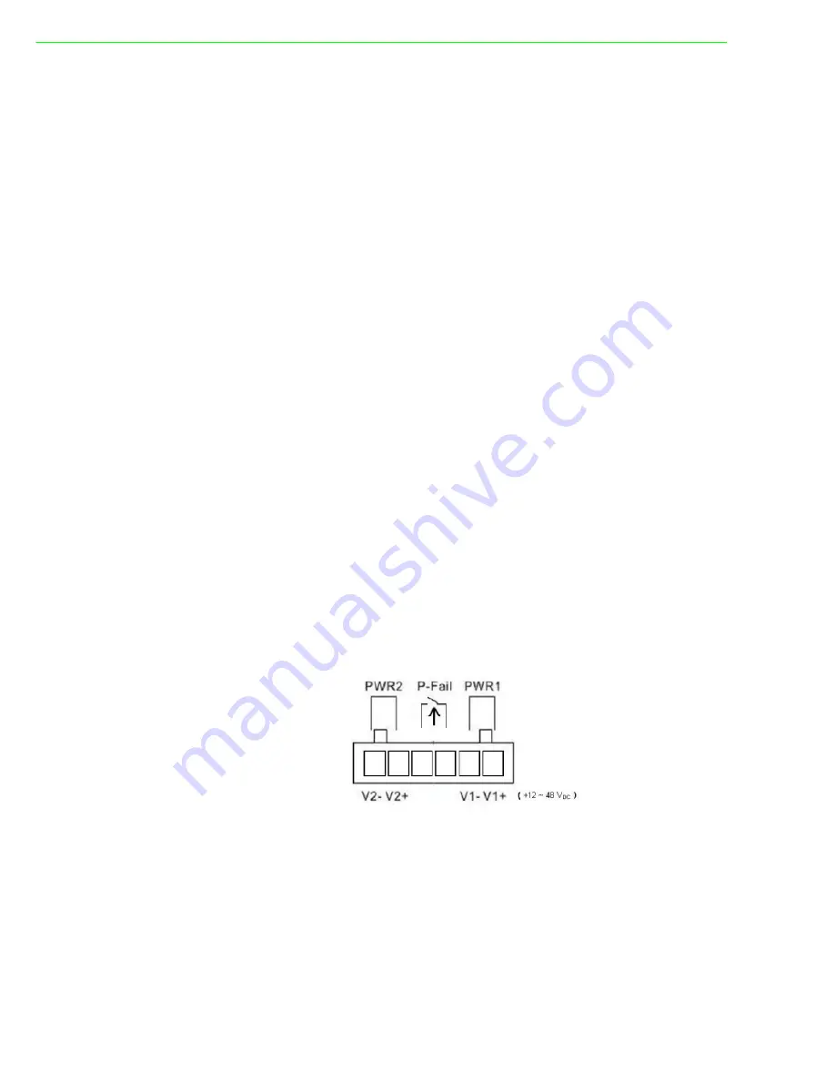
Power Connection
The EKI serial device server supports dual +12 ~ 48 VDC power inputs and power-
fail relay output.
You can connect an alarm indicator, buzzer or other signaling equipment through the
relay output. The relay opens if power input 1 or 2 fails ( “Open” means if you connect
relay output with an LED, the light would be off).


