background image

25


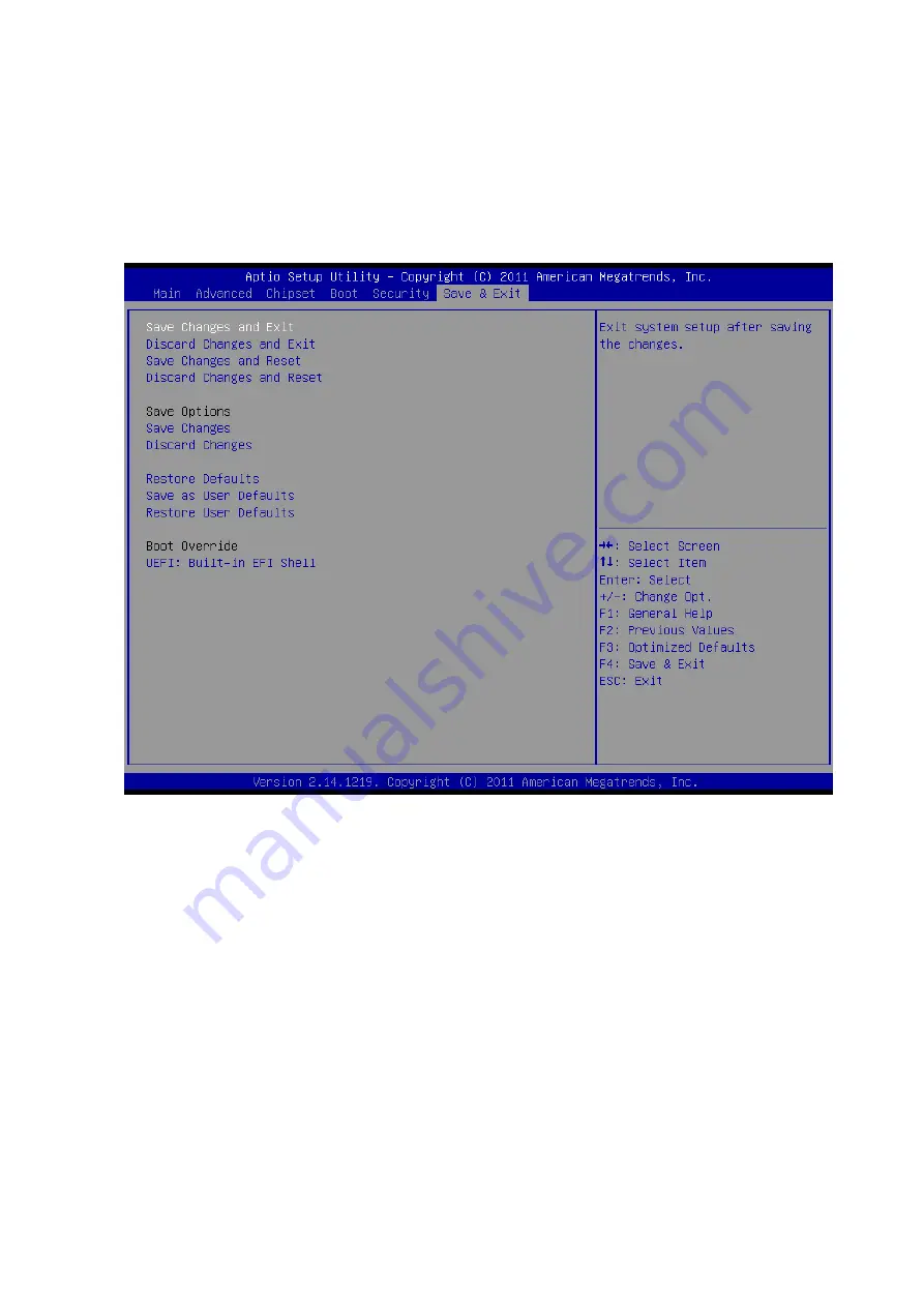
Save


Changes:


Save


Changes


done


so


far


to


any


of


the


setup


options.


Discard


Changes:


Discard


Changes


done


so


far


to


any


of


the


setup


options.


Restore


Defaults:


Restore/Load


Defaults


values


for


all


the


setup


options.


Save


as


User


Defaults:


Save


the


changes


done


so


far


as


User


Defaults.


Restore


User


Defaults:


Restore


the


User


Defaults


to


all


the


setup


options.


Figure.


28


Save


&


Exit


BIOS


Feature


Setup


Figure.


29


warning


message


about


system


protection


Summary of Contents for DS-561SQ-S7A1E

Page 1: ...1 DS 561SQ S7A1E DS 562SQ S6A1E Computer...

Page 2: ...ich may result from its use Acknowledgements Award is a trademark of Award Software International Inc IBM PC AT PS 2 and VGA are trademarks of International Business Machines Corporation Intel and ATO...

Page 3: ...t when the problem occurs 2 Call your dealer and describe the problem Please have your manual product and any helpful information readily available 3 If your product is diagnosed as defective obtain a...

Page 4: ...ating system version application software etc A complete description of the problem The exact wording of any error messages Warnings Cautions and Notes Warning Warnings indicate conditions which if no...

Page 5: ...lectrical shock 13 Never open the equipment For safety reasons the equipment should be opened only by qualified service personnel 14 If one of the following situations arises get the equipment checked...

Page 6: ...oduction DS 561 also supports 1x Giga LAN 1x COM ports 2x USB3 0 and 2x USB2 0 giving a great selection for data communication in display applications The entire design makes digital signage applicati...

Page 7: ...Ethernet Chipset 1 x Intel 82579LM Speed 100 1000 Mbps Interface 1 x RJ 45 jacks with LED Standard MACSec 802 1AE 9k Jumbo Frames and 2 Tx Rx queues 802 3az EEE Energy Efficient Ethernet Resolution DP...

Page 8: ...8 1 5 Mounting Kit 1 5 1 Dimension Figure 2 AC_TRAY_ANGLE_3 Figure 3 ANGLE_BASE...

Page 9: ...9 Figure 4 ANGLE_CB Figure 5 ANGLE_CT Warning Use suitable mounting apparatus to avoid risk of injury...

Page 10: ...on with brackets Figure 6 System with Brackets top view Figure 7 System with brackets bottom view Note This pair of wallmount bracket is designed for side of chassis and bottom side Reverse installati...

Page 11: ...1 6 Power Requirements 1 6 1 System Power 19V DC in Model name Output rated Tma degree C FSP065 RAB 19VDC 3 42A 40 5 FSP090 DMBB1 19VDC 4 74A 40 5 SPU63 105 19VDC 3 31A 40 5 ADP_65JH ABCD 19VDC 3 42A...

Page 12: ...E OF USED BATTERIES ACCORDING TO THE INSTRUCTIONS 1 7 Environmental Specifications 1 7 1 Operating Temperature 0 C 40 C 32 122 F 1 7 2 Relative Humidity 95 40 C non condensing 1 7 3 Storage Temperatur...

Page 13: ...a power ON OFF button on the front side Push this button to turn the system ON and OFF It also supports a 5 second delay soft power off Figure 8 Power ON OFF Button 2 2 2 COM Connector DS 561 provide...

Page 14: ...e RJ 45 LAN interface connector fully compliant with IEEE802 3u 10 100 1000 Base T CSMA CD standards The Ethernet port provides a standard RJ 45 jack connector with LED indicators to show its Active L...

Page 15: ...ant changes to the physical interface itself DisplayPort can be used to transmit audio and video simultaneously but each one is optional and can be transmitted without the other Figure 13 External con...

Page 16: ...ule secure HDD to HDD bracket with 2 screws 2 Install a HDD module into DS 561 then secure it with a screw Figure 14 HDD Installation Figure 15 System Installation SATA connector HDD bracket Screw 1 S...

Page 17: ...re 16 Memory Installation 2 3 3 WiFi Module Installation 1 Be easy to remove install on bottom cover like memory installation 2 Remove WiFi module cover first and replace WiFi module inside 3 Install...

Page 18: ...Main setup screen You can always return to the Main setup screen by selecting the Main tab The Main BIOS setup screen has two main frames The left frame displays all the options that can be configured...

Page 19: ...ation Hyper threading Enabled for Windows XP and Linux OS optimized for Hyper Threading Technology and Disabled for other OS OS not optimized for Hyper Threading Technology When disabled only one thre...

Page 20: ...to set up SATA devices configuration SATA Controller s Enable or disable SATA Device SATA Mode Selection Determines how SATA controller s operate The choice IDE AHCI RAID Figure 22 SATA Setting page P...

Page 21: ...een Hide Un Configure ME Confirmation OEMFLag Bit 6 Hide Un Configure ME without password Confirmation Prompt MEBx Debug Message Output OEMFLag Bit 14 Enable MEBx debug message Output Un Configure ME...

Page 22: ...is a workaround for 0Ses without EHCI hand off support The EHCI ownership change should be claimed by EHCI driver USB transfer time out The time out value for Control Bulk and Interrupt transfers The...

Page 23: ...0 COM Figure 25 Serial Port 0 Configuration setting CPU PPM Configuration CPU PPM Configuration Parameters EIST Enable Disable Intel SpeedStep Turbo Mode Turbo Mode CPU C3 Report Enable Disable CPU C3...

Page 24: ...r Password Set up Administrator Password When set limits access to BIOS Setup User Password Set User Password When set limits machine boot and access to BIOS Setup Figure 27 Security BIOS 3 2 5 Save E...

Page 25: ...f the setup options Restore Defaults Restore Load Defaults values for all the setup options Save as User Defaults Save the changes done so far as User Defaults Restore User Defaults Restore the User D...

Page 26: ......

Reviews: