background image

DS-270 User Manual

8

2.1

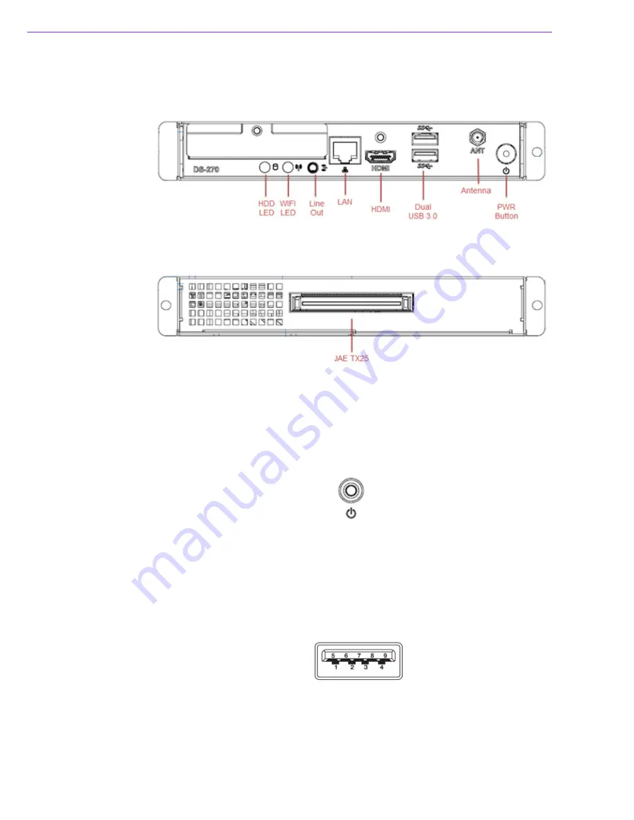
DS-270 I/O Connectors

2.1.1

Front I/O

2.1.2

Rear I/O

2.2

DS-270 External I/O Connectors

2.2.1

Power ON/OFF Button

DS-270 has a power ON/OFF button on the front side. Push this button to turn the
system ON and OFF. It also supports a 4 second delay soft power off.

Figure 2.1 Power ON/OFF Button

2.2.2

USB Connectors

DS-270 supports USB3.0 interface for 2pcs, which gives complete Plug and Play and
hot swapping capability for up to 127 external devices. The USB interface is compli-
ant with USB UHCI, Rev. 3.0. The USB interface supports Plug and Play, which
enables you to connect or disconnect a device without turning off the system.

Figure 2.2 USB Connector

Summary of Contents for DS-270

Page 1: ...User Manual DS 270 Advanced Graphic Performance OPS Computing Player with Intel J1900 Processor...

Page 2: ...s use Acknowledgements Award is a trademark of Award Software International Inc IBM PC AT PS 2 and VGA are trademarks of International Business Machines Cor poration Intel and ATOM are trademarks of I...

Page 3: ...ges displayed when the prob lem occurs 2 Call your dealer and describe the problem Please have the manual product and any relevant information readily available 3 If your product is diagnosed as defec...

Page 4: ...lem The exact wording of any error messages Warnings Cautions and Notes Packing List Before installation please ensure that the following items have been shipped 1 x DS 270 unit 1 x Simple Chinese Use...

Page 5: ...Never pour liquid into the openings This can cause fire or electrical shock 13 Never open the equipment For safety reasons the equipment should only be opened by qualified service personnel 14 If one...

Page 6: ...DS 270 User Manual vi...

Page 7: ...s 8 2 1 1 Front I O 8 2 1 2 Rear I O 8 2 2 DS 270 External I O Connectors 8 2 2 1 Power ON OFF Button 8 Figure 2 1 Power ON OFF Button 8 2 2 2 USB Connectors 8 Figure 2 2 USB Connector 8 Table 2 1 USB...

Page 8: ...ion setup screen 22 Figure 3 7 IDE Configuration setup screen 23 Figure 3 8 Miscellaneous Configuration setup screen 24 Figure 3 9 USB Configuration setup screen 25 Figure 3 10Intel TXE Configuration...

Page 9: ...Chapter 1 1 General Introduction This chapter gives background information regarding the DS 270 series...

Page 10: ...ed via a JAE 80 pin connector which supports HDMI DP UART and USB3 0 USB2 0 signals with the monitor Through UART it is easy to get status and manage ment reports DS 270 also has Giga LAN x1 HDMI x1 u...

Page 11: ...g timer interval 255 seconds depends on software setting I O Interface JAE TX25 80 pin connector x1 HDMI x1 USB 3 0 x2 compliant ports Audio phone jack for Line out x1 Full size mini PCIe internal x1...

Page 12: ...nal via OPS connector 1 5 2 RTC Battery 3 V 195 mAH BR2032 67 25 39 75 19 33 05 3 50 3 50 3 50 200 175 3 50 30 26 118 68 25 25 13 13 4 02 1 8 100 04 3 3 3 50 6 10 192 R 2 2 5 14 50 5 4 50 R 4 Note Thi...

Page 13: ...re 0 C 40 C 32 104 F w HDD 0 C 50 C 32 122 F w SSD 1 6 2 Relative Humidity 95 40 C non condensing 1 6 3 Storage Temperature 20 70 C 4 158 F 1 6 4 Vibration Loading During Operation HDD 0 2 Grms IEC 60...

Page 14: ...DS 270 User Manual 6...

Page 15: ...Chapter 2 2 Hardware Installation This chapter introduces external I O and the installation of DS 270 Hardware...

Page 16: ...t also supports a 4 second delay soft power off Figure 2 1 Power ON OFF Button 2 2 2 USB Connectors DS 270 supports USB3 0 interface for 2pcs which gives complete Plug and Play and hot swapping capabi...

Page 17: ...to show its Active Link status and speed status Figure 2 3 Ethernet Connector 2 2 4 Audio Connector Line Out Stereo speakers earphone or front surround speakers can be connected to the Line out jack...

Page 18: ...onnector which plugs JAE TX 24 to a mon itor Figure 2 6 JAE TX 25 80 pin Connector Table 2 3 HDMI Pin out Pin Signal Name 1 TMDS Data 2 2 TMDS Data 2 shield 3 TMDS Data 2 4 TMDS Data 1 5 TMDS Data 1 s...

Page 19: ...13 DDP_AUXN 53 GND 14 DDP_AUXP 54 StdA_SSRX 15 DDP_HPD 55 StdA_SSRX 16 GND 56 GND 17 TMD_CLK 57 StdA_SSTX 18 TMD_CLK 58 StdA_SSTX 19 GND 59 GND 20 TMDS0 60 USB_PN2 21 TMDS0 61 USB_PP2 22 GND 62 GND 23...

Page 20: ...emove 3 Install the storage module into DS 270 as below and connect the storage and SATA connector onto the device 4 Lastly fix the storage module onto DS 270 via a single screw Figure 2 7 HDD Install...

Page 21: ...the top silver cover of the fan 2 Undo the top storage screws and remove 3 Undo 4 screws on the top chassis and remove Please be careful to avoid any fan cable damage 4 Install memory into the SO DIMM...

Page 22: ...l 14 2 3 3 Memory 2 Installation 1 Remove 5 screws on the bottom chassis of DS 270 2 Install memory into the SO DIMM 2 slot 3 Lastly follow the steps to install the whole system Figure 2 9 Memory 2 In...

Page 23: ...nstallation 2 3 4 Mini PCIe Card 1 Remove 5 screws on the bottom chassis of DS 270 2 Install the mini PCIe card into the mini PCIe slot 3 Lastly follow the steps below and install the whole system Fig...

Page 24: ...DS 270 User Manual 16...

Page 25: ...Chapter 3 3 BIOS Settings This chapter introduces how to set BIOS configuration data...

Page 26: ...p screen by selecting the Main tab The Main BIOS setup screen has two main frames The left frame displays all the options that can be configured Options in blue can be configured and grayed out option...

Page 27: ...he items in the left frame of the screen such as CPU configuration to go to the sub menu for that item You can display an Advanced BIOS Setup option by highlighting it using the Arrow keys All Advance...

Page 28: ...DS 270 User Manual 20 ACPI Settings System ACPI Parameters Figure 3 3 ACPI setup screen Intel Smart Connect Technology Intel Smart Connect Technology settings Default is disabled...

Page 29: ...Chapter 3 BIOS Settings ITE8528E HW Monitor Monitor hardware status PC health status Figure 3 4 HW Monitor screen S5 RTC Wake Settings Enable disable system wake from S5 using RTC alarm Figure 3 5 S5...

Page 30: ...al 22 Serial Port Console Redirection Serial Port Console Redirection CPU Configuration CPU Configuration Parameters Figure 3 6 CPU Configuration setup screen PPM Configuration Enable disable CPU C st...

Page 31: ...23 DS 270 User Manual Chapter 3 BIOS Settings IDE Configuration IDE devices configuration Figure 3 7 IDE Configuration setup screen...

Page 32: ...nable disable the high precision event timer PCI Express Dynamic Clock Gating Enable disable PCIe dynamic clock gating OS Selection The OS selection should be set and matched with applied OS Figure 3...

Page 33: ...d for OS without EHCI hand off support The EHCI own ership change should be claimed by the EHCI driver USB Mass Storage Driver Support Enable disable USB mass storage driver support USB Transfer Timeo...

Page 34: ...DS 270 User Manual 26 Security Configuration Intel Anti Theft Technology configuration Figure 3 10 Intel TXE Configuration setup screen...

Page 35: ...ration settings XHCI Mode Enable disable the XHCI controller USB2 Link Power Management Enable disable USB2 link power manage ment PCI Express Configuration PCI Express Configuration settings LAN1 Con...

Page 36: ...BIOS Feature Setup Select the Security tab from the setup screen to enter the Security BIOS Setup screen Figure 3 11 Security Configuration setup screen Administrator Password Set Administrator Passw...

Page 37: ...Boot Configuration setup screen Setup Prompt Timeout Number of seconds to wait for setup activation key 65535 0xFFFF means indefinite waiting Bootup NumLock State Select the keyboard NumLock state Qui...

Page 38: ...set Reset the system after saving the changes Discard Changes and Reset Reset system setup without saving any changes Save Changes Save Changes done so far to any of the setup options Discard Changes...

Page 39: ...3 BIOS Settings Attempts to Launch EFI Shell application Shell efi from one of the available file system devices Reset System With ME Disable Mode MEUD000 ME will runs into the temporary disable mode...

Page 40: ...DS 270 User Manual 32...

Page 41: ...Chapter 4 4 Software This chapter highlights the OS installation prompts...

Page 42: ...XE manufacturing tools in EFI Shell or WinPE environment For Windows 7 OS only Intel TXEI Driver uses KMDF WDF 1 11 which is builtin on Windows 8 and Windows 8 1 How ever Windows 7 doesn t have it Ple...

Page 43: ...35 DS 270 User Manual Chapter 4 Software...

Page 44: ...subject to change without notice No part of this publication may be reproduced in any form or by any means such as electronically by photocopying recording or otherwise without the prior written perm...

Reviews: