


PPC-412 User Manual
12
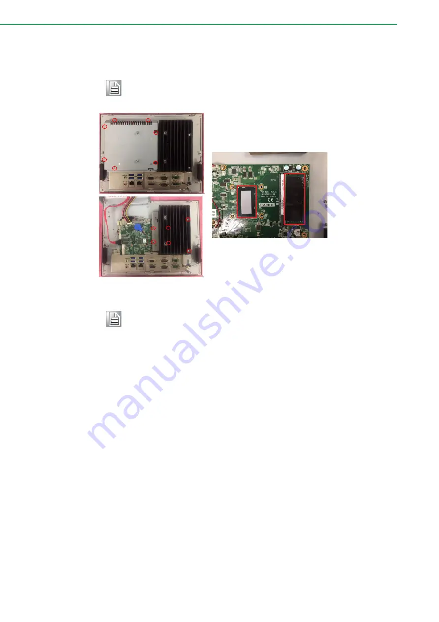
3.
Remove the yellow warning tag first. Then remove the screws as indicated in
the red circle. (See Figure 2.8), and take out the strength plate & CPU heat sink.
Note!
Take out the black and blue thermal grease from the accessory box (as
indicated in Figure 2.9). Attach the CPU heat sink and strength plate
after the grease is applied.
Figure 2.8
Figure 2.9
Note!
CPU cooler pad surface is isolated by anodization treatment to avoid
static electricity (CPU contact side excluded).
Summary of Contents for COASTIPC PPC-412
Page 1: ...User Manual PPC 412 Intel Core i Processor Based Microcomputer with 12 1 Color TFT LCD Display...
Page 14: ...PPC 412 User Manual 6 PPC Stand A1E Stand kit 98R3P321110 TPM 2 0 module...
Page 25: ...17 PPC 412 User Manual Chapter 2 System Installation Setup Figure 2 18 Figure 2 19 Figure 2 20...
Page 39: ...Chapter 4 4 Software Configuration Sections include Installing Drivers BIOS Setup Program...


