9
AIIS-3411 User Manual
C
ha
pte
r 2
H
ard
w
are
In
sta
lla
tio
n
2.1.1
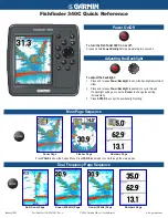
Power On/Off Button
The AIIS-3411 has a Power On/Off button with LED indicators on the front side that
show On status (green LED) and Off/Suspend status (orange LED). The Power but
-
ton supports dual functions: Soft Power - On/Off (Instant off or Delay 4 Seconds then
off), and Suspend.
Figure 2.3 Power On/Off Button
2.1.2
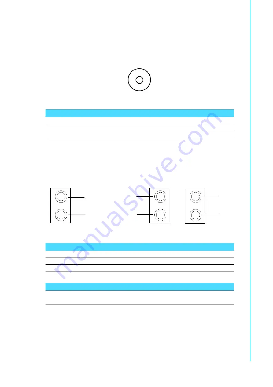
LED Indicators
There are two LEDs on the front panel that indicate system status: The temperature
LED is for system thermal alarm status; and HDD LED is for HDD and CFast disk sta
-
tus. In addition, there are four LEDs to indicate the connection of powered device via
PoE port.
Figure 2.4 LED Indicators
Table 2.1: Power Button Connector Pin Assignment
LED color
Status
Green
Power ON
Amber
S1/S4/S5
Table 2.2: LED Indicators (Thermal & HDD)
LED color
Function
Red
Over heating LED
Amber
SATA LED
Table 2.3: LED Indicator (PoE)
LED color
Function
Red
Connected Powered Device
HDD LED
Temp. LED
PoE
PoE
PoE
PoE
Summary of Contents for AIIS-3411 Series
Page 1: ...User Manual AIIS 3411 Machine Vision System Computer ...
Page 8: ...AIIS 3411 User Manual viii ...
Page 12: ...AIIS 3411 User Manual xii ...
Page 36: ...AIIS 3411 User Manual 24 ...
Page 37: ...Chapter 3 3 AMI BIOS Setup ...
Page 48: ...AIIS 3411 User Manual 36 3 2 2 8 Super IO Configuration Figure 3 11 Super IO Configuration ...
Page 64: ...AIIS 3411 User Manual 52 ...
Page 65: ...Chapter 4 4 Software Installation This chapter introduces driver installation ...
Page 69: ...57 AIIS 3411 User Manual Chapter 4 Software Installation ...
Page 70: ...AIIS 3411 User Manual 58 ...
Page 71: ...Appendix A A Programming the Watchdog Timer ...
Page 79: ...Appendix B B 32 bit DIO Signal Connections ...
Page 82: ...AIIS 3411 User Manual 70 ...
Page 83: ...Appendix C C Exploded Diagram Parts List ...
Page 84: ...AIIS 3411 User Manual 72 C 1 Exploded Diagram Figure C 1 Exploded Diagram ...