JUKI IT-10, Instruction Manual
The JUKI IT-10 is a high-performance sewing machine designed for professional use. With its advanced features and versatility, this cutting-edge product ensures seamless stitching for various fabrics. Experience optimum efficiency by referring to the comprehensive Instruction Manual available for free download from our website.
Share
Download


Reviews:
No comments
Related manuals for IT-10

MultiPASS L6000
Brand: Canon Pages: 39

MultiPASS 800
Brand: Canon Pages: 103

See3CAM 130
Brand: e-con Systems Pages: 9

AK85B
Brand: JUKI Pages: 5

SUPERABRASIVE 13G-X
Brand: lavina Pages: 27

Autopax PAX600H
Brand: Quasar Pages: 148

LS2-H6000-D
Brand: Unicorn Pages: 18

1002556 - 1020 Power Eagle
Brand: Nobles Pages: 55

MIG-350
Brand: zika Pages: 21
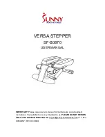
VERSA SF-S0870
Brand: Sunny Pages: 7

FOGSPRAY 3000 RGB
Brand: Mac Mah Pages: 31
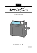
AeroCut X-Pro
Brand: UCHIDA Pages: 60

783
Brand: hobbylock Pages: 32

TitanCoil
Brand: MyBinding Pages: 7

SF-S1403
Brand: Sunny Health & Fitness Pages: 10

KX-TGA641
Brand: Panasonic Pages: 7

KX-TGA680
Brand: Panasonic Pages: 11

KX-TGA660
Brand: Panasonic Pages: 16


