background image

Page 28 / 56 

DLT-V6210 Manual V1.00 

Advantech-DLoG 

7. Operation

7.1.  Switching DLT-V6210 on/off 

The following factors determine how DLT-V6210 can be switched on and off: 


Is DLT-V6210 mounted on a automotive object and connected to the ignition signal? 


What are the automatic shut down settings that were defined in the MDevice configuration program? 

Switch on 

Switch DLT-V6210 on as follows, depending on the configuration: 


Press the <Power> button. 


Or: Through the ignition signal of the targeted object (depends on the automatic shutdown settings). 

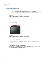
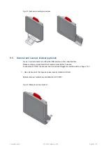
Fig. 7.1: <Power> button 

Switch off 

Switch DLT-V6210 off as follows, depending on the configuration: 


Press the <Power> button of the activated DLT-V6210. 


Or: Disconnect the supply voltage. 

NOTICE

: Devices will be hard-terminated (data loss possible). 


Or: Deactivate the ignition of the connected targeted object (depends on the automatic shut down 
settings). 

Time between switching off and on: 10 seconds 

After DLT-V6210 is shut down and switched off, it needs to wait at least 10 seconds until the device can 
react to a switch-on signal (<Power> button / ignition). 

Summary of Contents for DLT-V6210

Page 1: ...Manual DLT V6210 V 1 00 English 11 2019 ...

Page 2: ...We recognize all national and international trademarks and product names We reserve the right to modify the contents of this manual at any time and without prior notice DLoG GmbH assumes no liability for technical inaccuracies typographic errors or faults in this documentation DLoG GmbH also assumes no liability for damages caused directly or indirectly by the delivery performance or usage of this...

Page 3: ...f rail 24 6 4 Connecting the USB Ethernet and COM cables 25 6 4 1 USB cable 25 6 4 2 Ethernet cable 26 6 4 3 COM cable 26 6 5 Closing off unused cable openings 27 6 6 Attaching the cable cover 27 7 OPERATION 28 7 1 Switching DLT V6210 on off 28 7 2 Operating the touchscreen 29 7 3 Front keys and LEDs 30 7 3 1 Overview 30 7 4 Operating states 30 8 POWER SUPPLY UNIT POWER SUPPLY EXTERNAL CONNECTORS ...

Page 4: ...17 TECHNICAL CUSTOMER SUPPORT 54 18 RETURN SHIPMENT FORM 55 19 LIST OF FIGURES 56 ...

Page 5: ... Mounting steps skilled personnel Printed enclosed with the respective accessories User Manual Complete operating instructions skilled personnel PDF file Download Center at www advantech dlog com MDevice description Configuration tool skilled personnel PDF file Download Center at www advantech dlog com Pay attention to these manuals because they help avoid hazards reduce repair costs and downtimes...

Page 6: ...bodily injury will occur if this information is not observed WARNING means that death or severe bodily injury can occur if this information is not observed CAUTION means that slight bodily injury can occur if this information is not observed NOTICE Physical damage Information about possible physical damage TIP HINT Tips hints for using the product Note about additional information in manuals ...

Page 7: ...tech for further information DLT V6210 industrial PCs are not approved for using in EX zones potential explosion hazard are not approved for using on ships are not approved for using in life support systems or critical safety systems where system malfunction can lead to direct or indirect endangerment of human life Indented use includes the following The compliance with all safety instructions The...

Page 8: ...sonnel improperly operated and maintained not used as intended The owner operator commitments with regards to safety accident prevention regulations occupational safety are to be followed 2 3 Warranty conditions For DLT V6210 industrial PCs accessories the Advantech DLoG TOB regulations are valid section Liability for defects limitation period for claims Find details on the Advantech DLoG Internet...

Page 9: ... DLT V6210 Device name 9 digit ID Identification code characters from left to right Component Explanation 9 Core processor 7 x86 Bay Trail 10 Front unit P PCAP 11 Storage L 32G MLC CFast 12 Power supply 1 12 24 48 VDC 13 OS E WES8 P Win 7 pro 14 LTE 0 No LTE GPS 15 WIFI 0 No WIFI W WIFI 16 Revision number 0 17 RoHS appliance E oHS Input V A Input voltage of DC power supply unit nominal current S N...

Page 10: ...V6210 by the housing with both hands Never use the antenna cap as a handle It can break due to the weight involved Do not hold DLT V6210 by the strain relief rail Use the assistance of a second person for installation work 3 3 Storage Observe the permissible storage temperature range in the manual section 11 1 Environmental conditions 3 3 1 Protection of touchscreen during storage NOTICE Physical ...

Page 11: ...filled out return package slip must be enclosed with every DLT V6210 You can find this return package slip at the end of this manual and on the Internet at www advantech dlog com If you repack the device please ensure that the cling wrap in the cardboard frame is positioned towards the front of the device so that it can provide the proper protection ...

Page 12: ...e in the Download Center at www advantech dlog com 4 2 Wi Fi configuration optional Depending on the optional equipment and intended use of DLT V6210 the settings and access data for Wi Fi networks should be defined 4 2 1 Radio wave emission hazards This information applies exclusively to DLT V6210 devices that are equipped with wireless technology CAUTION Excessive radio wave emission due to inco...

Page 13: ...romagnetic radio frequency energy can interfere with technical devices Some technical equipment in hospitals and aircraft is not shielded against radio frequency energy Do not use DLT V6210 in aircraft or hospitals without receiving prior authorization Usage in both occasions is only permitted if such authorization has been obtained DLT V6210 industrial PCs can affect the functioning of implanted ...

Page 14: ...ation Observe the intended use of DLT V6210 e g not in potentially explosive areas not in life supporting facilities Ensure that the deployment location of DLT V6210 complies with the permissible environmental conditions WARNING Risk of accident on the targeted objects due to limited field of view of the user User s field of vision must remain free During installation reserve sufficient space for ...

Page 15: ...Advantech DLoG Ensure that ball and socket bases and mounting brackets are always attached correctly Please observe the mounting instructions supplied with the optional brackets DANGER Risk of accident on the target objects due to unexpected emergency stop because of electroconductive connection of DLT V6210 to the targeted object chassis Due to a variety of technical properties of forklifts and f...

Page 16: ...sk of injury due to weight and sharp edged parts DLT V6210 can fall down and cause injuries due to its weight The strain relief rail can have sharp edges and cause cutting injuries Always hold DLT V6210 by the housing with both hands Never use the antenna cap as a handle It can break due to the weight involved Do not hold DLT V6210 by the strain relief rail Use the assistance of a second person fo...

Page 17: ... the following sequence for the mechanical and electrical installation 1 Determine a suitable mounting position for DLT V6210 2 Secure device mounting at the targeted object RAM Mount etc 3 Connect external accessories to DLT V6210 4 Install an easily accessible disconnecting device such as a switch close to the device 5 Connect all cables 6 Close DLT V6210 with cable cover 7 Mount DLT V6210 on th...

Page 18: ...ical shock due to lack of disconnecting device DLT V6210 industrial PCs are not equipped with disconnecting devices that are accessible from outside they do not have switches To enable the devices to be quickly disconnected from the power supply in emergency situations Install an easily accessible disconnecting device such as a switch close to the device Make sure that the disconnecting device dis...

Page 19: ...h off DLT V6210 there is a risk of electrical shock Install DLT V6210 and the EMERGENCY OFF switch so that DLT V6210 also switches off when the EMERGENCY OFF switch is operated NOTICE Physical damage Overvoltage on DLT V6210 when charging the targeted object s battery DLT V6210 must be disconnected from the battery while the battery is being charged Or it must be ensured that the maximum permitted...

Page 20: ...Select the appropriate slot on the connector panel of DLT V6210 Check and test which order of the cables routing is the best to fit in the cable compartment 6 2 1 Material required Cable sealing set scope of delivery cable cover Cable cover Rubber seal Cable clips Screws Tools Hexagon screwdriver size 3 Philips screwdriver size 3 ...

Page 21: ...tc Make sure that the power supply cables are running without kinks and protected securely protected against crushing and abrading DLT V6210 may only be connected to a SELV circuit Safety Extra Low Voltage The SELV circuit is a secondary circuit that is designed to protect the voltage from exceeding the safe value when operation runs correctly or a single error occurs The DC connecting cable must ...

Page 22: ...e targeted object s chassis Connect the power supply cable of DLT V6210 as directly as possible to the battery and not to the power supply lines e g the engine power supply which a great deal of interference or otherwise affected by consumers Connecting DLT V6210 to large electrical loads such as converters for the forklift motor may result in random restarts malfunctions and or irreparable damage...

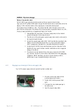
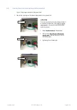
Page 23: ...the power supply cable to the ground bolt ATTENTION To make sure the device is grounding correctly it is important to follow the correct order to put the components on the ground bolt as below from inside to outside 1 Place toothed washer first internal 2 Then put the Ring Tongue of the power supply cable flat side faces DLT V6210 connector panel 3 Tightening the nut hand tight 1 2 3 ...

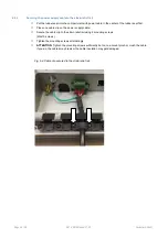
Page 24: ...eal first Place one cable clip on the power supply cable Secure the cable clip to the strain relief rail using 2 mounting screws M3x10 screws Tighten the mounting screws alternatingly ATTENTION Tighten the mounting screws sufficiently but on no account pinch or crush the cable If you do the cables may break or the cable insulation may get damaged Fig 6 4 Cable clip secured to the strain relief rai...

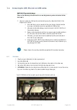
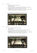
Page 25: ...r the start of DLT V6210 Otherwise you must ensure that the backflow from the external device to DLT V6210 cannot take place Only power up DLT V6210 when all devices are completely connected and DLT V6210 is closed correctly remember the cable cover Otherwise you may damage DLT V6210 Please observe the mounting instructions supplied with the optional accessory 6 4 1 USB cable Plug the required USB...

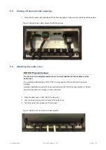
Page 26: ...les may break or the cable insulation may get damaged Fig 6 6 Ethernet cable on the connector panel secured to the strain relief rail 6 4 3 COM cable Plug the required COM cable into the associated port Insert the COM cable Put the rubber seal into the compartment with COM cable in themiddle of the rubber seal Secure the COM cable to the strain relief rail with cable clips and screws ATTENTION Tig...

Page 27: ...tely sealed due to incorrect attachment of the cables and the cable cover The protection class category of DLT V6210 is only ensured if the cable cover is properly installed Improper installation can result in liquid penetrating into DLT V6210 during operation This will cause the risk of short circuiting corrosion and wear Place the cable cover in DLT V6210 housing slot Lock the screws loosely int...

Page 28: ...n Or Through the ignition signal of the targeted object depends on the automatic shutdown settings Fig 7 1 Power button Switch off Switch DLT V6210 off as follows depending on the configuration Press the Power button of the activated DLT V6210 Or Disconnect the supply voltage NOTICE Devices will be hard terminated data loss possible Or Deactivate the ignition of the connected targeted object depen...

Page 29: ...rface of the touchscreen Ensure that the touchscreen surface is not influenced by high voltages or static electricity Do not use excessive force when touching the touchscreens and do not hit or press hard If the device with the touchscreen is placed down Place a clean soft cloth underneath Operating the touchscreen Clean dry fingers Clean dry soft gloves Suitable touch stylus with capacitive elect...

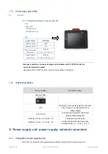
Page 30: ...itch off no voltage supply STATIC ON Computer start up normal operational state shutdown delay time Blinking 0 2 sec on 0 8 sec off Temperature sensor faulty Blinking 0 5 sec on 0 5 sec off Ambient temperature lies beyong the permitted range i e 30 or 50 C 8 Power supply unit power supply external connectors 8 1 Integrated power supply unit DLT V6210 is equipped with a galvanically separated integ...

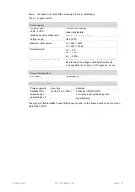
Page 31: ... 24V 1 75A 48V 0 875A Connection to SELV circuit only The SELV circuit is a secondary circuit that is designed to protect from the voltage exceeding the safe value when operation runs correctly or if a single error occurs Power consumption DLT V6210 Typically 34 W Power supply unit fuses Power supply unit Fuse type Example Advantech Dlog owned design power supply unit 5 x 20 mm 8 A 250 V LittleFus...

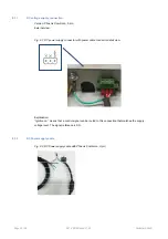
Page 32: ...ernal view Fig 8 1 DC power supply connector with power cable connector detail view Explanation Ignition on means that a control signal can be routed to this connection that matches the supply voltage level The signal reference is DC 8 1 2 DC Power supply cable Fig 8 2 DC Power supply cable with Phoenix Combicon 3 pin ...

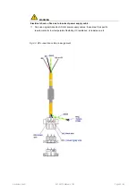
Page 33: ...Electrical shock or fire due to incorrect power supply cable Only use original Advantech DLoG power supply cables these meet the specific requirements for low temperature flexibility UV resistance oil resistance etc Fig 8 3 DC connection cable pin assignment ...

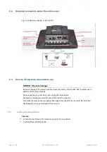
Page 34: ...e DLT V6210 system and in particular the Wi Fi functionality The antenna cap may only remain open during the service work No objects or liquids may enter the opened DLT V6210 during this Only when the antenna cap is properly closed again may operation be resumed the protection class category is only ensured again after doing so 8 3 1 Antenna cap opening closing Opening Loosen the two screws of the...

Page 35: ...he antenna cap seal must not be damaged it must be seated correctly in the groove Tighten the two screws of the antenna cap again 1 Nm torque 8 3 2 CFast slot There is a CFast slot under the antenna cap Exercise special care when removing and re inserting CFast card Only use CFast cards that have been approved by Advantech DLoG ...

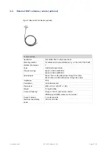
Page 36: ...al Technical data Application Wi Fi IEEE 802 11 ac b g n Dual Band Diversity Number of antennas 2 Type Omnidirectional antenna Directionality Optimized for the DLT V6210 housing Frequency range Band 1 2400 to 2485 MHz Band 2 5150 to 5875 MHz Antenna gain Max 5 dBi without loss through the cable Impedance 50 Ω Polarization Vertical Horizontal Maximum transmitting power 100 mW 20 dBm ...

Page 37: ...nnas 1 Type Omnidirectional antenna Frequency range Band 1 2400 to 4900 MHz Band 2 4900 to 6000 MHz Antenna gain Band 1 Max 4 dBi without loss through the cable Band 2 Max 6 5 dBi without loss through the cable Impedance 50 Ω Polarization Vertical Horizontal Dimensions Ø 86 x 43 mm Ø 3 39 x 1 69 Weight 0 3 kg 0 66 lbs Connector labeling N type or TNC N jack female bottom RSMA plug for RSMA socket ...

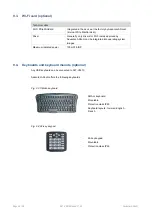
Page 38: ... Fi cards approved by Advantech DLoG can be integrated into operating system images Maximum radiated power 100 mW EIRP 9 4 Keyboards and keyboard mounts optional Any USB keyboard can be connected to DLT V6210 Advantech DLoG offers the following keyboards Fig 9 3 SMALL keyboard SMALL keyboard Mountable Protection class IP65 Keyboard layouts German English French Fig 9 4 24 key keypad 24 key keypad ...

Page 39: ... either the USB interface or the serial interface Please contact your Advantech DLoG sales representative if needed If connected to COM1 the scanner can be powered through the interface with a voltage of 5 V Use only scanners that have been approved by Advantech DLoG Optional scanner brackets are available for DLT V6210 Fig 9 6 Example scanner bracket ...

Page 40: ...t your Advantech DLoG sales representative if needed Use only touch stylus that have been approved by Advantech DLoG Fig 9 7 Example touch stylus for PCT touchscreen 9 7 USB recovery stick optional The optional Advantech DLoG recovery stick allows images to be backed up and restored onto DLT V6210 when necessary backup recovery Please contact your Advantech DLoG sales representative if needed ...

Page 41: ...ernal temperature reaches a critical level shutdown of the operating system will be carried out The computer will remain switched off until the temperature is once again within the permitted range If the ignition input is grounded or isolated during normal operation of DLT V6210 the device will switch to a delayed shut off state The device will continue to operate normally in this state until the ...

Page 42: ...pond appropriately to WM_QUERYENDSESSION i e the backup data must be saved without user confirmation and within the preset time 10 3 Configuration The MDevice program is used for the configuration of the automatic shut down under MS Windows The MDevice manual can be found online in the download center at www advantech dlog com ...

Page 43: ...ion and shock resistance Class 5M3 according to EN 60721 3 5 US Highway Truck according to MIL STD 810F IP protection class IP65 11 2 Projected capacitive touchscreen PCT Technical data Type Projected capacitive touchscreen Construction Glass film film Surface Hardness 9 H at 500 g according to JIS K 5400 Impact Energy Resistance IK08 5 joule according to ECN62262 Mechanical properties Chemically ...

Page 44: ... flashing activity Problems with data transmission via LAN Ethernet If problems occur during data transmission over LAN Ethernet e g data is lost or not detected the cause of these problems may be the cable is too long Depending on the cable layout and interference from the environment it may be impossible to use the cable length of 100 m given in the specification IEEE 802 3 standard The solution...

Page 45: ...lling patterns for the RAM attachment and swivel joint brackets are located on the rear side of DLT V6210 Dimensions without add ons in mm Need to use M6 screws and the length of thread should be between 8 to 10mm depending on the bracket thinkness to decide CAUTION Risk of injury due to using unsuitable mounting apparatus To ensure that the device can be mounted and secured safely must follow thi...

Page 46: ...Page 46 56 DLT V6210 Manual V1 00 Advantech DLoG Fig 11 3 Position VESA drill holes of DLT V6210 Support 75mm VESA dimension 75mm 75mm ...

Page 47: ...seated in the associated holder RAM mount mounting bracket and the mounting screws are not loose Also check whether the bracket is secured stably to the respective deployment location This is particularly important if DLT V6210 is installed on any automotive object Check whether all connected cables are secured and the cable cover shuts tightly WARNING Risk of accident due to unstable attachment o...

Page 48: ...le cleaners for example contain ammonia Do not use any abrasive glass cleaner or cloths that could scratch the touchscreen Cleaning the housing Ensure that DLT V6210 is switched off and currentless Clean the housing with a slightly dampened cloth Do not use compressed air a high pressure cleaner or vacuum cleaner as this can damage the surface Using a high pressure cleaner poses the additional ris...

Page 49: ... systems Windows 7 Pro Windows 8 1 Industry and WE8S do permit recalibration of the touchscreen via software Menu Control Panel Tablet PC Settings This resets the sensitivity of the touchscreen to an operating system default setting which can result in poorer detection of taps on the screen You can use Reset to reset the software recalibration Please contact DLoG GmbH if DLT V6210 malfunctions You...

Page 50: ...losion hazard are not approved for using on ships are not approved for using in life support systems or critical safety systems where system malfunction can lead to the direct or indirect endangerment of human life Observe the permissible environmental conditions Observe correct voltage range 14 2 Mobile application Please observe the following chapters in this manual 5 1 Safety notice observe bef...

Page 51: ... experienced radio TV technician for help CAUTION Radio frequency exposure In order to comply with the FCC requirements regarding radio frequency exposure from transmission devices The antenna has to be kept at least 20 cm away from people Any change or modification which is not expressly approved in the corresponding pages can lead to the withdrawal of the operating license for this device 15 1 R...

Page 52: ...ezéseket Norsk Norwegian Dette utstyret er i samsvar med de grunnleggende krav og andre relevante bestemmelser i EU direktiv 2014 53 EU EF Polski Polish Urządzenie jest zgodne z ogólnymi wymaganiami oraz szczególnymi warunkami określonymi Dyrektywą UE 2014 53 EU Português Portuguese Este equipamento está em conformidade com os requisitos essenciais e outras provisões relevantes da Directiva 2014 5...

Page 53: ...Advantech DLoG DLT V6210 Manual V1 00 Page 53 56 15 3 Declaration of conformity ...

Page 54: ...ns is required Please contact the responsible authorities in your country region to find out about the applicable regulations if necessary 17 Technical customer support If you experience technical difficulties please consult your distributor or contact the technical services department at Advantech DLoG s headquarters Phone 49 89 41 11 91 999 email helpdesk advantech dlog com Manufacturer address ...

Page 55: ...er E Mail Type s of unit s returned Serial number s of the unit s returned The units have not been returned as they are currently being used However the following parts are missing Unit was already damaged on delivery please enclose a copy of the delivery note Delivery was incomplete Missing parts The following error occurs when operating the unit Separate error report is enclosed ...

Page 56: ...blind plugs 27 Fig 6 9 Cable cover closed and screwed together 27 Fig 7 1 Power button 28 Fig 7 2 Operating elements Front keys and LED 30 Fig 8 1 DC power supply connector with power cable connector detail view 32 Fig 8 2 DC Power supply cable with Phoenix Combicon 3 pin 32 Fig 8 3 DC connection cable pin assignment 33 Fig 8 4 External connectors of DLT V6210 34 Fig 8 5 Antenna cap opened 35 Fig ...

Reviews: