6
SETUP
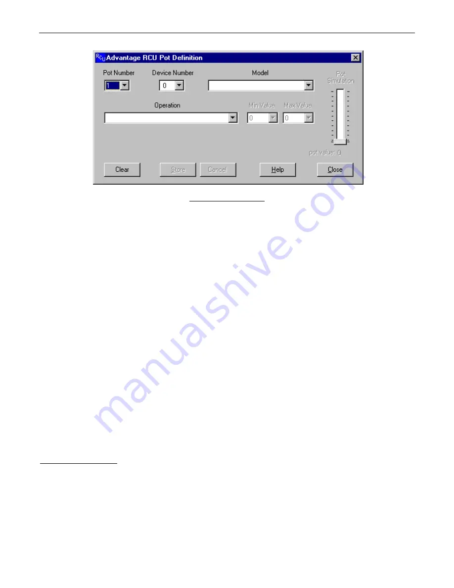
POT DEFINITION SCREEN
Up to 23 potentiometers may be connected to the Remote Control input port of the RCU. Each pot may be programmed to perform a
specific control function for a specific product. The programming process is performed using the Pot Definition Screen. Each product that
is linked to the RCU must have a unique device number. When creating a pot definition, you must specify the device number of the
product which that pot will be controlling. You must also specify the model of the product (VRAM, MSP22e, etc.). Once you have specified
the model, a list of available operations appears in the “Operation” list box. The list of operations changes depending upon which model is
selected. Most operations also allow you to specify a minimum value and a maximum value for the pot. If you do not override the default
values shown, the entire range of pot travel will correspond directly to the entire volume range that is possible for the specified operation.
By specifying a Min Value and/or a Max Value, you may restrict the range of volume levels for the pot. For example, each volume control
on an VRAM has 32 settings (or ‘steps’), ranging from a minimum value of 0 to a maximum value of 31. If you set Min Value to 3 and Max
Value to 28, then the fully counter-clockwise position of the pot will correspond to volume step 3 and the fully clockwise position of the pot
will correspond to volume step 28. A “Pot Simulation” fader appears on the Pot Definition Screen. This fader provides a convenient
method to test the pot definition as it is being created. Using the mouse to move the fader knob simulates the movement of the actual
potentiometer which is being defined. During an on-line session, moving the Pot Simulation fader knob will cause BiampWin to transmit
the appropriate character string commands to the specified product.
NOTE:
RS-232 level commands from other sources, including the
Pot Simulation fader, may conflict with actual pot settings. However, these conflicts are resolved as soon as the pot is again manipulated.
If the specified model is either a VRAM/VRAMeq or an SPM522D, then a “Use Logic Input for Muting” checkbox appears. With these
models, if you wish to use a pot as a volume control AND use a logic input to perform muting functions for the pot, you should select the
“Use Logic Input for Muting” checkbox and an appropriate logic input definition will automatically be created for you. This links the
operation of the logic input and the pot, allowing for cooperative control.
NOTE:
“Use Logic Input for Muting” is defined to mute when a
switch closes, and un-mute when the switch opens. Therefore, a ‘latching’ switch will maintain the selected muting status (muted or un-
muted), whereas a ‘momentary’ switch will temporarily mute (only while the switch is held closed).
Other forms of muting are available,
which behave differently when used in conjunction with a pot (see Logic Input Definition Screen on next page). However, these forms of
muting may cause conflicts, such as un-muting when the pot is manipulated, and un-muting to levels established by means other than the
pot (RS-232 commands, Pot Simulation fader, product software, etc.). In some cases, these forms of muting may actually be considered
desirable. When a definition has been established for a particular pot, an icon and device number will appear above the fader on the Main
Screen. The icon and device number indicate which device the pot is programmed to control. When the mouse pointer is positioned over
the fader, a pop-up ‘hint’ appears which provides a detailed description of the function which the pot is programmed to perform.
Connecting Pots to the RCU: The RCU is designed to be used with linear taper pots. The resistance value of the pots can be as low as
5K ohms or as high as 50K ohms. Pins 1 through 23 of the “Remote Control” connector on the RCU are for pot inputs. Pin 24 is a
reference voltage output (which is approxi5 volts DC), and pin 25 is ground. The ‘high’ (clockwise) side of all pots should be
connected to the reference voltage output on pin 24 of the remote control connector. The ‘low’ (counter-clockwise) side of all pots should
be connected to ground on pin 25 of the remote control connector. The wiper of each pot should be connected to the pin corresponding to
the pot number (1 through 23). In some cases, the wiper could be connected to more than one pin if you want to control more than one
volume level with the same pot (to simulate a ‘ganged’ pot).


