Advanced Instruments, Inc
10
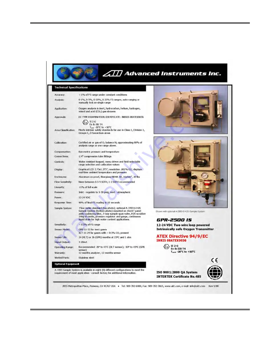
4. Features & Specifications
Page 1: ...ection calibration and system functions Display Graphical LCD 2 75 x 1 375 resolution 0 001 displays real time ambient temperature and pressure Enclosure NEMA Type 3R for rain in outdoor applications UL NEMA 4X ATEX Flow Not flow sensitive recommended flow rate 1 2 SCFH Linearity 1 of full scale Pressure Inlet regulate to 5 30 psig to deliver 1 2 SCFH flow vent atmospheric Power 18 24 VDC Response...
Page 2: ...struments Inc 2855 Metropolitan Place Pomona California 91767 USA Tel 909 392 6900 Fax 909 392 3665 e mail info aii1 com GPR 2800 IS PPM Oxygen Transmitter Shown with Optional A 3393 6 Sample System Owner s Manual ...
Page 3: ...sion Proofing Electrical Connections Appendix A Correlating readings LCD display to 4 20mA signal output Appendix B H2S Scrubber Sample System Media MSDS Appendix F Maintenance H2S Scrubber Coalescing Filter Appendix G The appendices referenced above are an integral part of the documentation installation and maintenance of this analyzer to comply with all applicable directives It is important that...
Page 4: ...smitter for superior performance and minimal cost of ownership This transmitter was tested thoroughly by the manufacturer prior to shipment for best performance However modern electronic devices do require service from time to time The warranty included herein plus a staff of trained professional technicians to quickly service your transmitter is your assurance that we stand behind every transmitt...
Page 5: ...ning This symbol is used throughout the Owner s Manual to Warn and alert the user of the presence of electrostatic discharge Danger This symbol is used throughout the Owner s Manual to identify sources of immediate Danger such as the presence of hazardous voltages Read Instructions Before operating the transmitter read the instructions Retain Instructions The safety precautions and operating instr...
Page 6: ...Advanced Instruments Inc 5 2 Quality Control Certification ...
Page 7: ... by the manufacturer Wipe off dust and dirt from the outside of the unit with a soft damp cloth then dry immediately Do not use solvents or chemicals Nonuse Periods If the transmitter is equipped with a range switch advance the switch to the OFF position and disconnect the power when the transmitter is left unused for a long period of time Installation This analyzer has been constructed in complia...
Page 8: ...ld not be immersed in any liquid Care should be taken so that liquids are not spilled into and objects do not fall into the inside of the analyzer Handling Do not use force when using the switches knobs or other mechanical components Before moving your analyzer be sure to disconnect the wiring power cord and any cables connected to the output terminals of the analyzer Sample Pressure and Flow All ...
Page 9: ...tional external sample pump may be used upstream of the sensor to push the sample across the sensor and out to atmosphere For PPM oxygen measurements an optional external sampling pump should be positioned downstream of the sensor to draw the sample from the process by the sensor and out to atmosphere A flow meter is generally not necessary to obtain the recommended flow rate with most sampling pu...
Page 10: ...tube fittings The sample inlet tubing must be metallic preferably SS The sample vent line may be of SS or hard plastic tubing with low gas permeability Power Supply power to the analyzer only as rated by the specification or markings on the analyzer enclosure The GPR 2800 IS 1800 IS is a two wire loop powered analyzer The input power must be between 12 24 VDC The wiring that connects the analyzer ...
Page 11: ...Advanced Instruments Inc 10 4 Features Specifications ...
Page 12: ...nals for incoming power signal output and intrinsic safety barriers are mounted on a PCB housed in an explosion proof enclosure The two sets of electronics are interconnected using an explosion proof Y fitting explosion proof packing fiber and sealing cement see Appendix A Once connected the intrinsic safety barriers limit the amount of power that flows to and from the signal processing electronic...
Page 13: ...now range from 32 months to ten years with faster response times and greater stability Another significant development involves expanding the operating temperature range for percentage range sensors from 30 C to 50 C Contact factory for more specific information about your application The PPM sensors recover from an upset condition to low PPM level in a matter of few minutes These sensors show exc...
Page 14: ... the same Temperature The rate at which oxygen molecules diffuse into the sensor is controlled by a Teflon membrane otherwise known as an oxygen diffusion limiting barrier and all diffusion processes are temperature sensitive the fact the sensor s electrical output will vary with temperature is normal This variation is relatively constant 2 5 per ºC A temperature compensation circuit employing a t...
Page 15: ...rements close to 100 O2 Conversely an error during a span adjustment close to the top end of the range e g at 100 is reduced proportionately for measurements of oxygen concentrations near the bottom end of the range Graph B represents a constant error over the entire measuring range This error is generally associated with the measuring e g LCD and or calibrating devices e g current simulator or cu...
Page 16: ...er size screws and anchors Caution Do not remove or discard the gaskets from either the Ex enclosure or the fiberglass enclosure Failure to reinstall either of the gaskets will void the NEMA 4 rating and the immunity to RFI EMI The transmitters design provides immunity from RFI EMI by maintaining a good conductive contact between the two halves of the enclosures via a conductive gasket the smaller...
Page 17: ...rts of the analyzer Set the SAMPLE SPAN and the ZERO gas pressure between 5 30 psig Select sample gas and allow it to flow through the transmitters and set the flow rate to1 2 SCFH Note If equipped with the optional H2S sample conditioning system Regulate the pressure so that it does not exceed 30 psig Flow rates of 1 5 SCFH cause no appreciable change in the oxygen reading However flow rates abov...
Page 18: ...on of the incoming power see Appendix A this configuration of the GPR 1800 IS 2800 IS conforms to the ATEX directives for equipments for use in hazardous area The analyzer meets the following area classification II 2 G Ex d ib ib IIB T4 Tamb 20 C to 50 C Ex enclosure for power input The GPR 2800 IS 1800 IS also meets the intrinsic safety standards required for use in Class 1 Division 1 Group C D h...
Page 19: ...asure the 4 20 mA signal output connect an ammeter as illustrated below To convert the 4 20 mA in to 1 5 VDC place a 250 Ohms resister in place of the current meter and measure the voltage across the resister Fuse 100 mA Power 12 24 VDC 4 20 mA Measuring Device Transmitter Caution To prevent accidental damage to the analyzer it is highly recommended that the user supply an additional Fuse rated at...
Page 20: ...h local regulations Avoid electrostatic discharge Clean all surfaces with a damp cloth only Procedure Remove the two 2 clamps securing the right side corners and open the door of the fiber glass enclosure Loosen the bolt at the bottom of the sensor housing by using 5 16 ranch provided Twist the upper section of the housing 90 degree and pull it up until it clears the bottom section of the sensor h...
Page 21: ...pressure regulator to set the span gas pressure between 5 and 30 psig A flow meter to set the flow between 1 5 SCFH Suitable tube fittings and a 4 6 ft length of 1 8 dia metal tubing to connect the regulator to the flow meter inlet Suitable tube fittings and a 4 6 ft length of 1 8 dia metal tubing to connect from the flow meter vent to tube fitting designated as SAMPLE IN or SPAN IN at the analyze...
Page 22: ...forms several self diagnostic system status checks termed as START UP TEST as illustrated below START UP TEST ELECTRONICS PASS TEMP SENSOR PASS BAROMETRIC SENSOR PASS REV 2 14 After self diagnostic tests the analyzer turns itself into the sampling mode And displays oxygen contents the sensor is exposed to the analysis range the ambient temperature and pressurel 0 3 AUTO SAMPLING 0 1 RANGE 76 F 100...
Page 23: ...nded For example calibration with ambient air 20 9 oxygen the analyzer will automatically turn into 0 25 range However the user can also select the MANUAL SAMPLE mode for calibration but the span gas must not exceed the full scale of the manual range selected for example a span gas with an 8 oxygen concentration in nitrogen would dictate the use of the 0 10 full scale range for calibration Auto Sa...
Page 24: ...MANUAL SAMPLE CALIBRATION CONFIG ALARMS BYPASS ALARMS MANUAL RANGE 25 10 5 1 Advance the reverse shade cursor using the ARROW keys to highlight the desired MANUAL RANGE Press the ENTER key to select the highlighted menu option The following displays appear with the range selected and oxygen concentration of the sample gas MANUAL RANGE 25 10 5 1 5 3 MANUAL RANGE 0 10 RANGE 76 F 100 KPA If the oxyge...
Page 25: ...zer is checked prior to shipment However due to the fact that the factory sample system conditions differ from that of the user no ZERO OFFSET adjustment is made at the factory Span Calibration Involves periodically see Intervals section below checking and or adjusting the electronics to the sensor s signal output at a given oxygen standard The frequency of calibration varies with the application ...
Page 26: ...e value of the span gas the impact of the offset on accuracy is minor but the addition allows the oxygen sensor to continue to purge down and avoid negative readings after calibration When installing a new oxygen sensor and calibrating with air allow 2 3 minutes for the sensor to equilibrate in ambient air from storage packaging Failure to do so can introduce error in calibration Zero Calibration ...
Page 27: ...50 of the lowest range this will indicate that the integrity of the sensor the analyzer sample system and the sample line bringing in the sample gas is maintained Access the MAIN MENU by pressing the MENU key Advance the reverse shade cursor using the ARROW keys to highlight CALIBRATION Press the ENTER key to select the highlighted menu option The following displays appear MAIN MENU AUTO SAMPLE MA...
Page 28: ...ure that the accumulative zero offset never exceeds 50 of the lowest range limit To perform Default Zero Access the MAIN MENU by pressing the MENU key Advance the reverse shade cursor using the ARROW keys to highlight CALIBRATION Press the ENTER key to select the highlighted menu option The following displays appear MAIN MENU AUTO SAMPLE MANUAL SAMPLE CALIBRATION CONFIG ALARMS BYPASS ALARMS CALIBR...
Page 29: ...ade cursor using the ARROW keys to highlight DEFAULT ZERO Press the ENTER key to select the highlighted menu option and the following display appears 100 0 OUTPUT ZERO OFFSET PRESS UP OR DOWN TO CHANGE VALUE ENTER TO SAVE MENU TO RETURN The default setting of 100 illustrates no adjustment to the analog output signal Compute the adjustment value as described in Appendix B or consult the factory The...
Page 30: ...ssing the MENU key Advance the reverse shade cursor using the ARROW keys to highlight AUTO SAMPLE Press the ENTER key to select the highlighted menu option The following displays appear MAIN MENU AUTO SAMPLE MANUAL SAMPLE CALIBRATION CONFIG ALARMS BYPASS ALARMS 0 3 AUTO SAMPLING 0 1 RANGE 76 F 100 KP Return to the MAIN MENU by pressing the MENU key Advance the reverse shade cursor using the ARROW ...
Page 31: ...ing is within 50 of the span gas value If the O2 reading is outside of this limit by pressing ENTER to accept calibration will result in FAILED CALIBRATION and the analyzer will return to the Sample mode without completing Span calibration The calibration routine will result in the following messages PASSED CALIBRATION OR FAILED CALIBRATION If the calibration is unsuccessful return to the SAMPLING...
Page 32: ...he highlighted menu option The following displays appears MAIN MENU AUTO SAMPLE MANUAL SAMPLE CALIBRATION CONFIG ALARMS BYPASS ALARMS CALIBRATION SPAN CALIBRATE ZERO CALIBRATE DEFAULT SPAN DEFAULT ZERO OUTPUT SPAN OUTPUT ZERO Advance the reverse shade cursor using the ARROW keys to highlight DEFAULT SPAN Press the ENTER key to select the highlighted menu option The following displays appear and af...
Page 33: ...sor right or press the MENU key to advance the underline cursor left to reach to the desired digit of the OUTPUT SPAN OFFSET value Press the ARROW keys to enter the OUTPUT SPAN OFFSET value Repeat above steps until the complete OUTPUT SPAN OFFSET value has been entered Save the adjustment value by pressing the ENTER key or abort by pressing the MENU key The system returns to the SAMPLING mode Samp...
Page 34: ...olumn pressure unless done gradually Avoid excessive flow rates above 5 SCFH which may generate backpressure on the sensor Avoid sudden releases of backpressure that can severely damage the sensor Avoid the collection of particulates liquids or condensation on the sensor that could block the diffusion of oxygen into the sensor If the transmitter is equipped with an optional integral sampling pump ...
Page 35: ...o service Only trained personnel with the authorization of their supervisor should conduct maintenance 7 Spare Parts Recommended spare parts for the GPR 1800 IS Oxygen Transmitter Item No Description GPR 11 32 Oxygen Sensor for measuring O2 in inert gases XLT 11 24 Oxygen Sensor for measuring O2 in gases containing CO2 Other spare parts Item No Description B 2762 A 2 14 Sensor housing upper sectio...
Page 36: ...k Qualify zero gas using portable transmitter Replace sensor Replace sensor High O2 reading after installing or replacing sensor Transmitter calibrated before sensor stabilized caused by 1 Prolonged exposure to ambient air worse if sensor was un shorted 2 Air leak in sample system connection s 3 Abnormality in zero gas Allow O2 reading to stabilize before making the span calibration adjustment Con...
Page 37: ...akage from sensor Liquid covering sensing area Improper sensor selection Presence of interference gases Unauthorized maintenance Sensor nearing end of life Calibrate the transmitter calibrate at pressure and temperature of sample Clean contacts with alcohol minimize exposure time of MS sensor to ambient air to extent possible Replace sensor and return sensor to the factory for warranty determinati...
Page 38: ...eam of the transmitter to draw sample from a process at atmospheric pressure or under a slight vacuum Placing a vacuum on the sensor in excess 10 of water column is strongly discouraged A premature adjustment of the ZERO OFFSET potentiometer is a common problem Avoid drawing a vacuum on the sensor a pressurized sensor may not leak but still produce negative readings From MAIN MENU select DEFAULT Z...
Page 39: ...lyzers and sensors purchased worldwide It is the only one we will give and it sets forth all our responsibilities There are no other express warranties This warranty is limited to the first customer who submits a claim for a given serial number and or the above warranty period Under no circumstances will the warranty extend to more than one customer or beyond the warranty period Limitations Advanc...
Page 40: ...s 1 0 Potassium Hydroxide or Acetic Acid Lead CAS Number Potassium Hydroxide KOH 1310 58 3 or Acetic Acid 64 19 7 Lead Pb 7439 92 1 Chemical Synonym and Family Potassium Hydroxide KOH Base or Acetic Acid CH3CO2H Acid Lead Pb Metal General Requirements Use Potassium Hydroxide or Acetic Acid electrolyte Lead anode Handling Rubber or latex gloves safety glasses Storage Indefinitely Physical Propertie...
Page 41: ...h federal state and local regulations Health Hazard Information Primary Route s of Entry Ingestion eye and skin contact Exposure Limits Potassium Hydroxide ACGIH TLV 2 mg cubic meter or Acetic Acid ACGIH TLV OSHA PEL 10 TWA Lead OSHA PEL 05 mg cubic meter Ingestion Electrolyte could be harmful or fatal if swallowed KOH Oral LD50 RAT 2433 mg kg or Acetic Acid Oral LD50 RAT 6620 mg kg Eye Electrolyt...
Page 42: ...Do not remove the sensor s protective Teflon and PCB coverings Do not probe the sensor with sharp objects Wash hands thoroughly after handling Avoid contact with eyes skin and clothing Empty sensor body may contain hazardous residue Transportation Not applicable ...
Page 43: ...fitting to prevent leakage of the liquid cement Leave enough space in the fitting for length equivalent to the inside diameter of the conduit but not less then 5 8 Caution Avoid getting in eyes or breathing dust Use barrier cream gloves and long sleeve shirts if dust or fiber is irritating Prolonged contact may cause lung eye or skin irritation Directions for use Explosion Proof Sealing Cement Tam...
Page 44: ...d breathing or ingestion may cause internal obstruction seek medical care Do not get into eyes or on skin if cement touches eyes or skin flush with water for 15 minutes Large amounts on skin when hardening may cause skin burn Use adequate ventilation To reorder sealing cement kit specify P N ENCL 1071 KIT ...
Page 45: ...4 20mA value the theoretical LCD value the adjustment value will be 100 b If the actual 4 20mA value the theoretical LCD value the adjustment value will be 100 4 Convert the actual reading of the LCD display to the theoretical 4 20mA as follows a Divide the actual or percent LCD reading by the value of the span gas available b Multiply 16mA 20mA 4mA times the result of a c Add 4mA plus the result ...
Page 46: ...O RETURN Enter the calculated adjustment value Note Once the initial adjustment is made and checked at the PLC it may be necessary to fine tune the initial adjustment by repeating Any additional percent error must be added or subtracted from the initial adjustment value 000 0 OUTPUT ZERO OFFSET PRESS UP OR DOWN TO CHANGE VALUE ENTER TO SAVE MENU TO RETURN Press the ENTER key to advance the underli...
Page 47: ...Enter the calculated adjustment value refer to example described above Note Once the initial adjustment is made and checked at the PLC it may be necessary to fine tune the initial adjustment by repeating Any additional percent error must be added or subtracted from the initial adjustment value 064 0 OUTPUT SPAN OFFSET PRESS UP OR DOWN TO CHANGE VALUE ENTER TO SAVE MENU TO RETURN Press the ENTER ke...
Page 48: ...Advanced Instruments Inc 47 ...
Page 49: ...Advanced Instruments Inc 48 ...
Page 50: ...Advanced Instruments Inc 49 ...
Page 51: ...ng disengages Carefully remove the stainless tubing from the top and bottom of the scrubber Carefully pull the scrubber from its mounting clip which is attached to the back panel Once the scrubber is free hold the scrubber with one hand and using the 1 open end or adjustable wrench with the other hand turn the 1 nut counter clockwise and remove the 1 nut from the scrubber There is no need to remov...
Page 52: ...ng The filter element screws into the head section carefully turn it counter clockwise and remove it from the head Using the damp cloth clean the inside of the bowl and the o ring before reassembling apply a very thin coat of lubricant to the o ring Reverse the above steps to re assemble the filter ...