Advanced Instruments, Inc.
8. Trouble Shooting
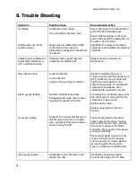
Symptom
Possible Cause
Recommended Action
No Display
Reading does not reflect
expected values
Inadequate power supply
Incorrect polarity of power input
Sensor was not calibrated at similar
vent pressure, flow rate and
temperature anticipated in the sample
gas stream
Ensure that power to the transmitter is
within the recommended range
Ensure that the polarity of the input
power matches with the designation on
the power input terminal
Recalibrate the analyzer at ambient
conditions that resemble with sampling
conditions.
Unable to span calibrate the
sensor with ambient air or
with a certified span gas
Indication sensor signal output is
outside the acceptable limit
Replace sensor, see Section 6 -
Maintenance.
Slow response time
Erratic oxygen reading
No oxygen reading
Longer sample line
Low sample flow
Liquid covering sensing membrane
Presence of interference gases.
Damaged sensor cable and or sensor
housing bring signal to the PCB
No signal from sensor possibly due to
defective/used up sensor or broken
wire connections from sensor cable or
sensor housing to PCB
Reduce the sample tubing to a
minimum, set sample flow between 1-2
SCFH, gently remove any liquid that
might have accumulated on the
sensor’s sensing side. If condensable
components are present, use a
coalescing filter upstream of sensor
Consult factory, interfering gas such as
H2S might need to removed from the
sample gas, replace sensor.
Replace sensor cable
Replace upper section of sensor
housing
Check for any physical damage to
sensor cable and or sensor housing.
Use a voltmeter and check continuity
from sensor housing to the Molex
connector (the connector from sensor
housing to the PCB)
Check sensor signal output in air (by
using a voltmeter (set to measure
micro-amp current). Sensor signal in
air must be within 40-60 uA (%
sensor) or 450-900 uA (PPM sensor).
High oxygen reading
Inadequate control of pressure and
sample flow rate
Set sample gas pressure within
recommended range of 5-30 PSIG
31

