background image

2855 Metropolitan Place, Pomona, CA 91767 USA   

   Tel: 909-392-6900, Fax: 909-392-3665, www.aii1.com, e-mail: [email protected]     Rev 10/15 

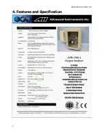
Technical Specifications * 

Accuracy: 

< 2% of FS range under constant conditions 

Analysis: 

0-1%, 0-5%, 0-10%, 0-25% FS ranges; auto-ranging or 
fixed single range 

Application: 

Oxygen analysis in inert, hydrocarbon, helium, hydrogen, 
mixed and acid (CO

2

) gas streams 

Area Classification:  General purpose 

Alarms: 

Two user configurable alarms: magnetic coil relays rated 
3A at 100 VAC, field programmable alarm time delays, 
alarm bypass for calibration and system fail alarm 

Calibration: 

Max interval

3 months. Air calibrate with clean source 

of certified span gas, compressed, or ambient (20.9% 
O2) air on 0-25% range. 

Compensation: 

Barometric pressure and temperature 

Connections: 

1/8" compression tube fittings 

Controls: 

Water resistant keypad; menu driven range selection, 
calibration and system functions 

Display: 

Graphical LCD 2.75” x 1.375”; resolution 0.001%; 


displays real time ambient temperature and pressure 

Enclosure: 

Fiberglass NEMA 4X, 4 x 9 x 3", 8 lbs. 

Flow Sensitivity: 

Not flow sensitive, 1-2 SCFH recommended 

Linearity: 

±1% of full scale 

Pressure: 

Inlet - regulate to 5-30 psig to deliver 1-2 SCFH flow;  
vent - atmospheric 

Power: 

12-28 VDC non-loop or 110-220 VAC 

Response Time: 

90% of final reading in 13 seconds 

Sample System: 

None 

Sensitivity: 

< 0.5% of FS range 

Sensor Model: 

GPR-11-32-4  for non-acid (CO2) gas streams;  
XLT-11-24-4  for gases containing > 0.5% CO2 

Sensor Life: 

GPR-11-32-4  32 months in air at 25ºC and 1 atm 
XLT-11-24-4  32 months in air at 25ºC and 1 atm 

Signal Output: 

4-20mA  non-isolated or 1-5V; optional Modbus 

Operating Range:  5ºC to 45ºC (GPR sensor), -10

º

 to 45

º

C (XLT sensor) 

Warranty: 

12 months analyzer; 12 months sensor 

Wetted Parts: 

Stainless steel  

Optional Equipment 

Sample conditioning system - Contact factory. 

* Subject to change without notice 


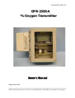
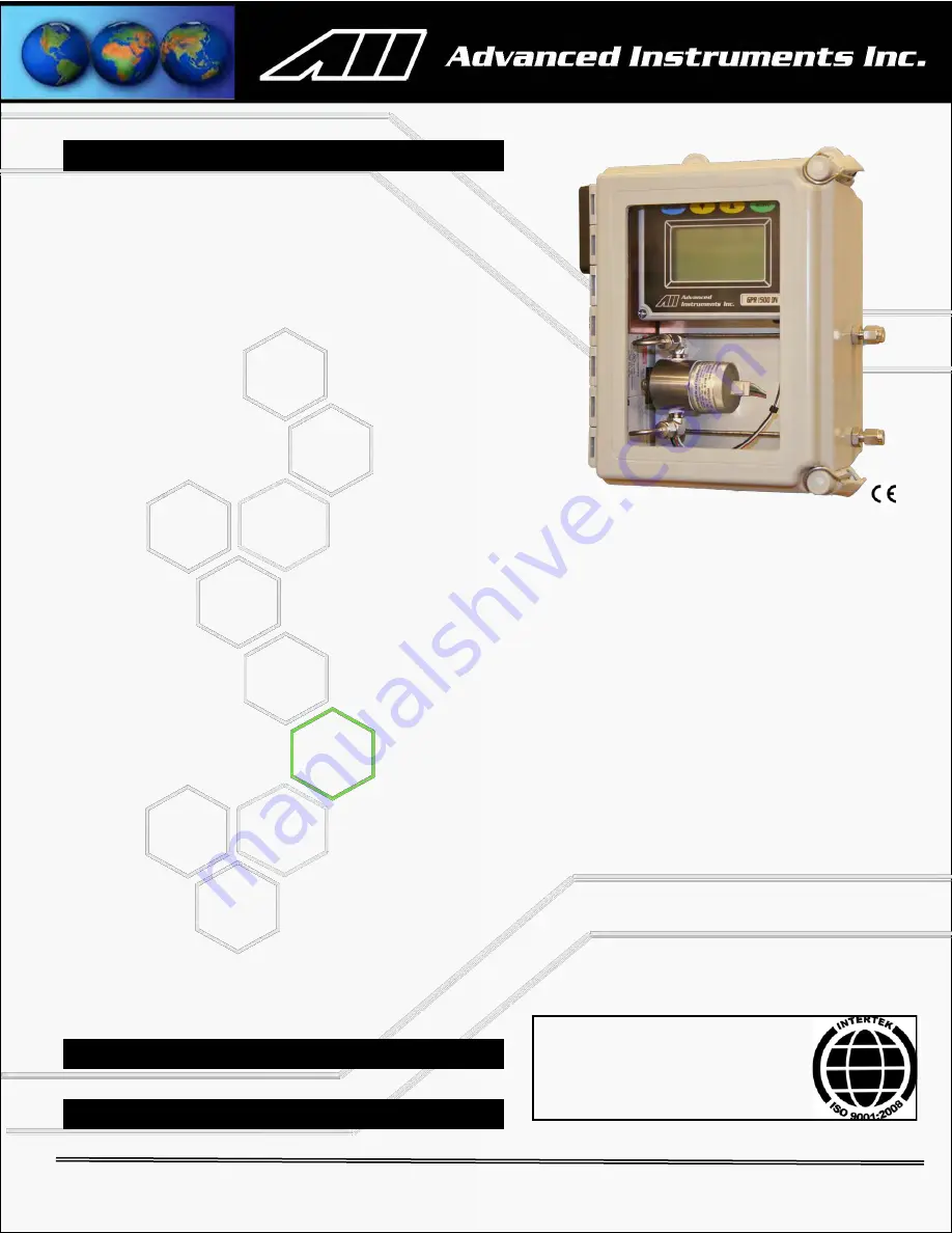
GPR-2500 A 

Oxygen Analyzer 


12-24 VDC Non-Loop or 110-220 VAC 

 Powered Oxygen Analyzer 


Advanced Galvanic Sensor Technology with 

Optional Sample Systems 

2 Field Selectable Alarm Setpoints


12

-

24 VDC or 110

-

220 VAC Power


4

-

20 mA Signal Output


Sensitivity 0.5% Full Scale


4 Ranges Standard


Auto Ranging or Single Fixed


Stainless Steel Wetted Parts


ISO 9001:2008 Certified


INTERTEK Certificate No. 485 

Summary of Contents for GPR-2500A

Page 1: ...ass NEMA 4X 4 x 9 x 3 8 lbs Flow Sensitivity Not flow sensitive 1 2 SCFH recommended Linearity 1 of full scale Pressure Inlet regulate to 5 30 psig to deliver 1 2 SCFH flow vent atmospheric Power 12 28 VDC non loop or 110 220 VAC Response Time 90 of final reading in 13 seconds Sample System None Sensitivity 0 5 of FS range Sensor Model GPR 11 32 4 for non acid CO2 gas streams XLT 11 24 4 for gases...

Page 2: ...Advanced Instruments Inc GPR 2500A Oxygen Transmitter Owner s Manual Revised June 2014 2855 Metropolitan Place Pomona CA 91767 USA Tel 909 392 6900 Fax 909 392 3665 e mail info aii2 com www aii2 com ...

Page 3: ...s Inc Table of Contents Introduction 1 Quality Control Certification 2 Safety 3 Features Specifications 4 Operation 5 Maintenance 6 Spare Parts 7 Troubleshooting 8 Warranty 9 Material Safety Data Sheets 10 Drawings A R 2 ...

Page 4: ...r was tested thoroughly by the manufacturer prior to shipment for best performance However all electronic devices do require service from time to time The warranty included herein plus a staff of trained professional technicians to quickly service your transmitter is your assurance that we stand behind every transmitter sold The serial number of this transmitter may be found on the inside the tran...

Page 5: ... Software rev Ranges 0 1 0 5 0 10 0 25 Power 12 24V DC Barometric pressure and temperature compensation NEMA 4X rated wall mount enclosure Test Pass Pass Set default zero Set default span 40uA Alarm delay Zero calibration Alarm bypass Span Calibration Alarm configurations ALARM 1 ALARM 2 Analog signal output 4 20mA full scale Alarm function ALARM 1 ALARM 2 Calibrates with adequate span adjustment ...

Page 6: ...ated either fitting can serve as inlet or vent and are intended to operate at positive sample pressure regulated between 5 30 psig Caution If equipped with a H2S scrubber as part of an optional sample conditioning system inlet pressure must not exceed 30 psig Outlet Pressure The sample gas must be vented to atmosphere or vent pipe with atmospheric pressure Installation Oxygen Sensor DO NOT open th...

Page 7: ...ppendix Avoid contact with any liquid or crystal type powder in or around the sensor or sensor housing as either could be a form of electrolyte Leaking sensors should be disposed of in accordance with local regulations Troubleshooting Consult the guidelines in Section 8 for advice on the common operating errors before concluding that your transmitter is faulty Do not attempt to service the transmi...

Page 8: ...Advanced Instruments Inc 4 Features and Specification 7 ...

Page 9: ...experience may vary due to the integrity of sample line connections dead volume and flow rate selected on all ranges under ambient monitoring conditions Sensitivity is typically 0 5 of full scale low range Oxygen readings may be recorded by an external device via the 0 1V signal output jack The circuit for the 4 20mA signal output and two adjustable alarms is powered by a DC DC transformer that re...

Page 10: ...r with integral metering valve positioned upstream of the sensor is recommended for controlling the sample flow rate between 1 5 SCFH If necessary a pressure regulator pressure regulator with a metallic diaphragm is recommended for optimum accuracy the use of more permeable materials may result in erroneous readings upstream of the flow control valve should be used to regulate the inlet pressure b...

Page 11: ...er column pressure unless done gradually Avoid excessive flow rates above 5 SCFH which generate backpressure on the sensor Avoid sudden releases of backpressure that can severely damage the sensor Avoid the collection of particulates liquids or condensation collect on the sensor that could block the diffusion of oxygen into the sensor If the transmitter is equipped with an optional integral sampli...

Page 12: ... A temperature compensation circuit employing a thermistor offsets this effect with an accuracy of 5 over the recommended operating temperature range or better and generates an output signal that is relatively independent of temperature Note There is no error if the calibration and sampling are performed at the same temperature or if the measurement is made immediately after calibration Lastly sma...

Page 13: ...s Note As described below zeroing the transmitter is recommended only for measurements below 1 and not practical for measurement ranges above 1 The low end sensitivity zero capability has been verified at the factory however no ZERO OFFSET adjustment has been made A factory adjustment would be meaningless because of the difference in sample systems and leakage factors between the factory set up an...

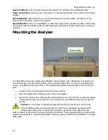
Page 14: ...plate with four 4 of the appropriate size screws To facilitate servicing the interior of the transmitters position it approximately 5 feet off ground level Loosen the four mounting pads at the rear of the enclosure Select four appropriate mounting screws customer supplied Secure the enclosure to a vertical surface approximately 5 feet from the floor or a level accessible to service personnel This ...

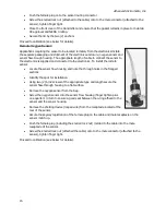
Page 15: ...ving your finger the restriction generates a vacuum on the sensor and may damage the sensor voiding the sensor warranty Procedure of Connecting Sample Gas Designate one of the bulkhead tube fittings as the VENT and the other as SAMPLE Regulate the sample span gas pressure to 5 30 PSIG Connect a 1 8 vent line to the compression fitting to be used for venting the sample Connect a 1 8 ZERO SPAN or SA...

Page 16: ...stall the remote sensor Locate the sensor flow housing and note the through holes in the flanged sections Identify the spot for installation Using two 2 6 32 screws of the appropriate type and length secure the sensor flow through housing to a flat surface Remove the oxygen sensor from the bag Screw the oxygen sensor into the sensor flow housing finger tighten plus one quarter 1 4 turn to ensure a...

Page 17: ... converter is internally powered and does not require external power DO NOT supply any voltage to either of the two terminals of the 4 20mA output connector Failure to do so will permanently damage the 4 20mA converter Procedure Remove the front cover of the junction box located on left side of the transmitters by removing the four 4 screws securing the cover and set them aside for reinstallation ...

Page 18: ...m the shipping container However when the application requires a remote sensor external to the electronics enclosure or other special circumstances the oxygen sensor will be packaged separately and must be installed prior to operating the transmitter If the sensor has not been installed at the factory it will be necessary to install the sensor in the field Note All transmitters must be calibrated ...

Page 19: ...necting the pressure regulator When installing the pressure regulator bleed the air filled regulator to flush air from the regulator before securing it on the cylinder When using a span gas always bleed the pressure regulator before opening the span gas to the analyzer this requires a bypass valve at the exit of the pressure regulator valve Note Always use a certified span gas with an oxygen conce...

Page 20: ...erly connected to the terminals inside the junction box the digital display responds instantaneously At power up the transmitter performs several diagnostic system status checks termed START UP TEST as illustrated below 12 24 VDC Power In START UP TEST ELECTRONICS PASS TEMP SENSOR PASS BAROMETRIC SENSOR PASS REV 2 15 19 ...

Page 21: ...n The GPR 2500A transmitter is equipped with four 4 standard measuring ranges see specification and provides users with a choice of sampling modes By accessing the MAIN MENU users may select either the AUTO SAMPLING ranging or MANUAL SAMPLING to lock on a single range mode Procedure Auto Sampling Access the MAIN MENU by pressing the MENU key Advance the reverse shade cursor using the ARROW keys to...

Page 22: ...ft back to the 0 10 range when the oxygen reading drops to 8 5 Procedure Manual Sampling Access the MAIN MENU by pressing the MENU key Advance the reverse shade cursor using the ARROW keys to highlight MANUAL SAMPLE Press the ENTER key to select the highlighted menu option The following displays appears Advance the reverse shade cursor using the ARROW keys to highlight the desired RANGE Press the ...

Page 23: ...calibration is recommended for measurements below 0 1 on the 0 1 range only At ranges above 0 1 the overall zero offset is negligible and does not contribute any error in measurements Procedure Zero calibration should precede the span calibration and once performed should not have to be repeated with subsequent span calibrations Normally zero calibrations are performed when a new sensor is install...

Page 24: ...le range available Thus the maximum zero calibration adjustment or zero offset for this analyzer is 0 6 oxygen Factory Default Zero The software will eliminate any previous zero calibration adjustment and display the actual signal output of the sensor at a specified oxygen concentration For example assuming a zero gas is introduced the display will reflect an oxygen reading representing basically ...

Page 25: ...erage oxygen sensor s signal output For example after factory default span when a span gas is introduced the micro processor will display oxygen reading within 50 of the span gas value when the sensor signal output is within its specification If the sensor s signal output is outside of its specification the oxygen reading will be beyond 50 of the span gas value This feature allows the user to test...

Page 26: ... span calibration Access the MAIN MENU by pressing the MENU key Advance the reverse shade cursor using the ARROW keys to highlight AUTO SAMPLE Press the ENTER key to select the highlighted menu option Advance the reverse shade cursor using the ARROW keys to highlight CALIBRATE and press ENTER The following displays appear Press the ENTER key to select the SPAN CALIBRATE option The following displa...

Page 27: ...owing displays showing either PASSED CALIBRATION OR FAILED CALIBRATION In either case the transmitter returns to the SAMPLING mode and resume sampling Disconnect the span gas line and replace it with sample gas line Wait 10 15 minutes to ensure the reading is stable and then proceed to sampling 20 01 SPAN CALIBRATION IN PROGRESS ENTER TO CALIBRATE MENU TO ABORT PASSED CALIBRATION FAILED CALIBRATIO...

Page 28: ...onsult the factory The true adjustment value must be determined empirically by trial and error Adjust the initial value to above 100 to increase the analog signal value or decrease it below 100 to decrease the analog signal Press the ENTER key to advance the underline cursor right or press the MENU key to advance the underline cursor left to reach to the desired digit of the OUTPUT ZERO OFFSET val...

Page 29: ... rate of 1 2 SCHF is recommended For sample gases under atmospheric or slightly negative pressure an optional sampling pump is recommended to push the sample through the transmitter Ensure that sample flow is within the recommended range if necessary use a flow control valve to set the sample flow Assure the sample is adequately vented for optimum response and recovery and safety Allow the oxygen ...

Page 30: ...to changes in oxygen concentration pressure and temperature To replace sensor follow the procedure outlined in the section Operation Serviceability Except for replacing the oxygen sensor there are no parts inside the transmitter for the operator to service Only trained personnel with the authorization of their supervisor should conduct maintenance Caution DO NOT open the oxygen sensor The sensor c...

Page 31: ...0A Other spare parts Item No Description A 2079 Bracket Sensor Mounting CONN 1014 Cable Sensor with Female Socket FITN 1018 Connector SS 1 8 MNPT to 1 8 Tube FITN 1039 Elbow SS 1 8 A 3051 Housing Flow Adaptor MTR 1010 Meter Digital Panel LCD Backlight A 2781 Nut Sensor Retaining A 1161 AIS 2 Rev C4 PCB Assembly Main Display A 1166 AIS 2 Rev H PCB Assembly Power Supply Interconnections 30 ...

Page 32: ...rence gases Damaged sensor cable and or sensor housing bring signal to the PCB No signal from sensor possibly due to defective used up sensor or broken wire connections from sensor cable or sensor housing to PCB Reduce the sample tubing to a minimum set sample flow between 1 2 SCFH gently remove any liquid that might have accumulated on the sensor s sensing side If condensable components are prese...

Page 33: ...tempting to Zero calibrate prematurely Set sample flow between 1 2 SCFH Vent sample to atmosphere If venting sample to a vent pipe with pressure above atmosphere consult factory for recommendations Qualify span gas with a secondary analyzer Check for any leakage in sample zero gas line Check the integrity of zero gas Set the gas flow rate between 1 2 SCFH Allow sufficient time for the oxygen readi...

Page 34: ...the product is fit for ordinary use are limited to one year from the date of shipment by manufacturer or purchase from a distributor with proof of purchase Advanced Instruments Inc will not pay for loss of time inconvenience loss of use of your Advanced Instruments Inc transmitter or property damage caused by your Advanced Instruments Inc transmitter or its failure to work any special incidental o...

Page 35: ...e all required parts under warranty at no charge to you but the distributor is an independent business and may render a service charge for their services Advanced Instruments Inc will not reimburse you or otherwise be responsible for those charges Return to Advanced Instruments Inc You may obtain warranty service by returning you transmitter postage prepaid to Advanced Instruments Inc 2855 Metropo...

Page 36: ...edients Carcinogens at levels 0 1 None Others at levels 1 0 Potassium Hydroxide Lead CAS Number Potassium Hydroxide KOH 1310 58 3 Lead Pb 7439 92 1 Chemical Synonym and Family Potassium Hydroxide KOH Base Lead Pb Metal Physical Properties Boiling Point Range 100 to 115 C Melting Point Range KOH 10 to 0 C Lead 327 C Freezing Point 40 to 0 C Molecular Weight KOH 56 Lead 207 Specific Gravity 1 09 20 ...

Page 37: ... wipe all surfaces repeatedly with water or wet paper towel Use a fresh towel each time Waste Disposal Method In accordance with federal state and local regulations for battery disposal Health Hazard Information Primary Route s of Entry Ingestion eye and skin contact Exposure Limits Potassium Hydroxide ACGIH TLV 2 mg cubic meter Lead OSHA PEL 05 mg cubic meter Effects of Exposure Ingestion Electro...

Page 38: ...erings Do not probe the sensor with sharp objects Wash hands thoroughly after handling Avoid contact with eyes skin and clothing Empty sensor body may contain hazardous residue Transportation Not applicable Product Identification Product Name Oxygen Sensor Models XLT Synonyms Galvanic Fuel Cell Electrochemical Transducer Manufacturer Analytical Industries Inc 2855 Metropolitan Place Pomona CA 9176...

Page 39: ...applicable Special Fire Fighting Procedures Not applicable Unusual Fire and Explosion Hazards Not applicable Reactivity Data Stability Stable Conditions Contributing to Instability None Incompatibility Avoid contact with strong bases Hazardous Decomposition Products Emits toxic fumes when heated Conditions to Avoid Heat Spill or Leak Steps if material is released Sensor is packaged in a sealed pro...

Page 40: ...r reproductive harm Lead acetate formed as the sensor is used is listed as a chemical known to the State of California to cause cancer Emergency First Aid Ingestion Do not induce vomiting Give plenty of cold water or if available milk Seek medical attention immediately Skin Contact Wash affected area repeatedly with plenty of water Remove contaminated clothing If burning persists seek medical atte...

Reviews: