background image

3  | 

P a g e

 - Ver. 1.0


OPTIONAL - IEEE-488 COMMAND LIST ................................................................................................................. 26


ETHERNET INITIAL PARAMETER SETUP VIA USB CONNECTION ............................................................................ 27


MONITORING WINDOW ................................................................................................................................... 30 

SAFETY INSTRUCTIONS 


BEFORE USING THIS EQUIPMENT 

Read this manual and become familiar with safety markings and instructions. 

Inspect unit for any sign of external damage. Do not use this equipment if there is physical damage or missing 

parts. 

Verify the input AC voltage to the main power supply 


INTENDED USE 

This product is intended for general laboratory use in a wide variety of industrial and scientific applications.   


RF OUTPUT LOAD & PROPER GROUNDING REQUIRED 

The RF output connector must be connected to a load before the AC switch is on. 

AC & RF power must be off before disconnecting the output load or other components. 

The main power source to the equipment must have an uninterrupted safety ground that has sufficient size to 

the power cord. 


REPAIR & MAINTENANCE 

All repair or maintenance work must be performed by a factory authorized technician in order to extend the 
operating life of this equipment and not to void any outstanding warranty


FORCED AIR COOLING 

This equipment requires forced air cooling.    All air inlets and outlets must be cleared and free of blocking at all 

time.  Insufficient air flow will result in damaged equipment. 


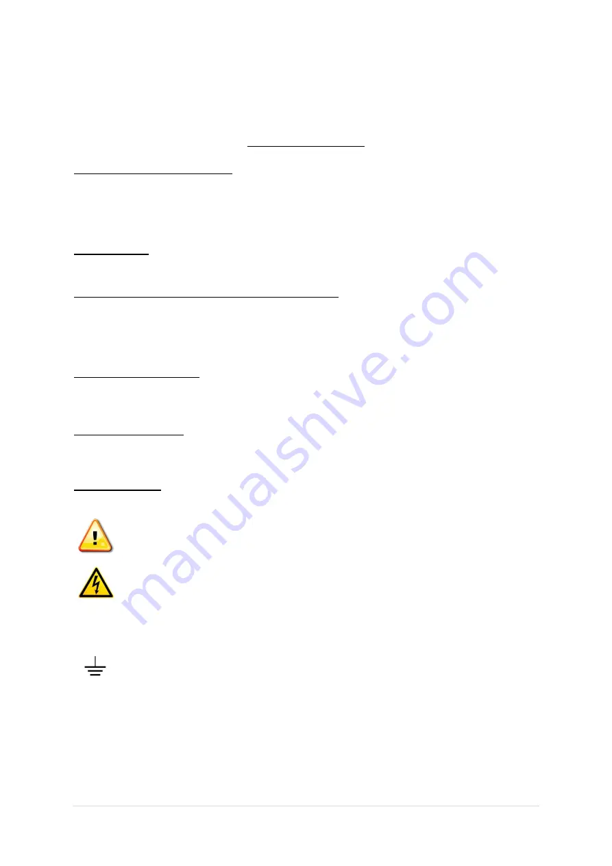
SAFETY SYMBOLS 


This symbol is marked on the equipment when it is necessary for the user to refer to the 

manual for important safety information. This symbol is indicated in the Table of Contents to 

assist in locating pertinent information. 


Dangerous voltages are present. Use extreme care


CAUTION

:   

The caution symbol denotes a potential hazard. Attention must be given to the statement to 

prevent damage, destruction or harm.


This symbol indicates protective earth terminal. 


Summary of Contents for AA-20M1G-50

Page 1: ...1 P a g e Ver 1 0 Instruction Manual and Quick Start Guide Exodus Advanced Communications Solid State RF Amplifier System AA 20M1G 50 20 1000 MHz 50 Watt Min 47 dB Min ...

Page 2: ...MITY 6 LIMITED WARRANTY 6 CONTACT INFORMATION 6 FRONT REAR PANEL DESCRIPTIONS 7 FRONT PANEL VIEW 7 REAR PANEL VIEW 8 SYSTEM OUTLINE VIEW 9 SYSTEM BLOCK DIAGRAM 10 SYSTEM VIEW TOP INTERIOR 11 SYSTEM VIEW BOTTOM 12 SYSTEM PARTS LIST 13 SYSTEM WIRING DIAGRAM 14 LOCAL CONTROLLER LCD INTERFACE 15 SCREEN 1 15 SCREEN 2 16 SCREEN 3 17 SCREEN 4 18 SCREEN 5 19 REMOTE CONTROLLER INTERFACE SOFTWARE 20 PRIMARY...

Page 3: ...urce to the equipment must have an uninterrupted safety ground that has sufficient size to the power cord REPAIR MAINTENANCE All repair or maintenance work must be performed by a factory authorized technician in order to extend the operating life of this equipment and not to void any outstanding warranty FORCED AIR COOLING This equipment requires forced air cooling All air inlets and outlets must ...

Page 4: ...0 Sec without damage Load VSWR Protection 1 1 minute at rated Pout ENVIRONMENTAL CHARACTERISTICS Parameter Specification Notes Operating Ambient Temperature 0 to 50 C Storage Temperature 40 to 85 C Relative Humidity 5 to 95 Non condensing MECHANICAL SPECIFICATIONS Parameter Specification Notes Dimensions W x H x D 430 x 88 x 562 mm 2U excluding handles Weight 10 kg RF Connectors In Out Type N Fema...

Page 5: ...mage Do not use this equipment if there is physical damage or missing parts Inspect all front and rear panel connectors for damage Inspect fans and their airways for any damage or blockings For a unit with a digital controller option the interface software USB is with the manual RF AC CABLE CONNECTION RF Input and Output connectors are Type N female connectors Use the standard AC cable that was su...

Page 6: ...placement of defective goods F O B factory of which Seller is modified in writing by Buyer within three 3 years following delivery thereof to Buyer and in no event will Seller be liable for incidental special or consequential damages Note One 1 year warranty for moving parts such as fans and power supplies The foregoing warranty is in lieu of all other warranties express or implied except as to ti...

Page 7: ...e Connector 2 RF INPUT System RF Input Connector N type Female Connector 3 FAULT LED System Fault LED Turn ON an LED when System Fault Over Input Over Temp Over Current Voltage Alarm VSWR Alarm 4 LCD DISPLAY 4 Touch screen LCD Display System Control LCD Panel 5 POWER SWITCH AC Power Switch AA 20M1G 50 POWER ON OFF FAULT 3 1 2 4 5 0dBm Input RF Sample ...

Page 8: ...or RJ 45 4 AC POWER CONNECTOR AC Power Input 100 240 VAC 50 60Hz IEC60320 14 Connector 5 DEBUG System Controller Debugging Female Connector Port access requires factory authorization 6 GPIB GPIB Communication Female Connector 7 RS 422 RS 422 Communication Female 9pin D Sub Connector P1 Rx P2 Rx P3 Tx P4 Tx P5 GND AA 20M1G 50 100 240 VAC 50 60Hz ETHERNET DEBUG RS 422 USB GPIB 1 12 13 24 6 7 5 1 2 3...

Page 9: ...9 P a g e Ver 1 0 SYSTEM OUTLINE VIEW AA 20M1G 50 SYSTEM OUTLINE POWER ON OFF FAULT 0dBm Input RF Sample 100 240 VAC 50 60Hz ETHERNET DEBUG RS 422 USB GPIB 1 12 13 24 50Ω Output AA 20M1G 50 AA 20M1G 50 ...

Page 10: ...ALE MINI USB TYPE FEMALE INPUT MODULE HPA MODULE COUPLER MODULE 1 R471 2 FRONT PANEL REAR PANEL TEMP MONITOR ATTEN CONTROL PS FAN FAN 1 5 GPIB TEMP SENSOR TEMP SENSE 5VDC 5VDC RS 232 IEEE 488 CONTROLLER IEEE 488 IEEE 488 IEEE 488 IEEE 488 FEMALE INPUT DETECT 5VDC E1 RS 422 RS 422 9PIN D SUB FEMALE REF DETECT R471 1 SW C N WHITE B L BLACK A GND GREEN N L GND POWER SUPPLY 750W V V PS GND AC 100 240V...

Page 11: ...11 P a g e Ver 1 0 SYSTEM VIEW TOP INTERIOR AA 20M1G 50 SYSTEM VIEW TOP INTERIOR Top Interior View M3 0 M3 0 M3 0 M3 0 M3 0 M3 0 1 2 13 14 7 15 17 16 3 2 1 11 20 20 12 19 8 14 18 4 5 6 9 10 13 ...

Page 12: ...12 P a g e Ver 1 0 SYSTEM VIEW BOTTOM INNER N A ...

Page 13: ...HPA Module 5 1 Fan Controller 6 1 Heat Sink 7 1 RF Detect Module 1 8 1 Coupler Module 2 9 1 Support 2 10 1 Coupler Module 1 11 2 60 x 25mm Cooling Fan 12 2 60mm Cooling Fan Guard 13 1 Temp Sensor 14 1 RF Detect Module 2 15 1 Power Supply 16 1 7P Terminal Block 17 1 Support 3 18 1 GPIB Module 19 1 System Controller 20 2 2U Handle ...

Page 14: ...LACK VDD SHUTDOWN 9 8 20 YELLOW 24 7 6 5 4 1 3 2 N C N C VDD GND 20 YELLOW 20 BLACK 20 GRAY GRAY 24 TERMINAL BLOCK 3A POWER SUPPLY V POWER SUPPLY V BROWN 24 CURRENT MONITOR CON J2 3 TEMP MONITOR CON J2 5 GREEN 24 POWER SUPPLY V POWER SUPPLY V FAN_CURR J7 1 LOCAL J7 2 REMOTE J7 3 FAULT J7 4 ENABLE J7 5 TEMP AL_IN J7 6 J7 7 J7 8 FAN CON P1 TERMINAL BLOCK 4B GREEN 24 GRAY 24 GRAY 24 FAULT LAMP P1 N C...

Page 15: ...ons system will automatically go to STANDBY mode and will display a RED FAULT line which is highlighted left top side of display An operator should click and check FAULT menu to review fault conditions No FAULT test at the top of the screen next to STANDBY FWD POWER Displays current output of the system RFL POWER or REV POWER Displays current reflected power at the output of system VSWR Based on F...

Page 16: ...ons it will display some or all of below internal system parameters STANDBY H _Min Sec It records total hours H M S of the system from the moment that an AC power switch is in ON position RADIATE H _Min Sec It records total hours H M S of the system from the moment that ONLINE button is pushed IP Displays the IP number of the amplifier PORT Displays the Port number ALLOWED TIME Allowed time is the...

Page 17: ...nables an operator to set the total gain of the system within 20 to 25dB range of maximum gain If a total system gain is 50dB maximum attenuation cannot exceed 50dB AG READ This button recalls and display a current attenuation level AG SET This button sets AGC value entered by an operator to the system NOTE Operator can always return to no attenuation by setting attenuation value to 0 1 0 1 1 0 1 ...

Page 18: ...evel ALC SET This button sets ALC value entered by an operator to the system NOTE Operator can always return to no ALC by pressing ALC OFF button 1 0 1 1 0 1 Operator can set ALC value by an increment of 1dB or 0 1dB ALC OFF ALC ON These buttons are used to turn on and off the ALC feature of the system By default ALC is OFF unless factory presetting is set for automatic activation for over power p...

Page 19: ...al components are detected OVER CURRENT Activates when irregular current consumption to the internal components are detected TEMPERATURE Activates when irregular temperatures of internal components or system level are detected Other custom parameters per customer requirements STAT or STATUS Under normal operating conditions no fault STAT windows will display CLEAR In an event of fault conditions S...

Page 20: ...ion button d dBm Watt Display dBm Watt status e TABLE ALE FAULT COMM Display menu status f TABLE TABLE menu button g ALC ALC menu button h FAULT FAULT menu button i COMM COMM menu button j EXIT Button to exit the program k Display status of the TABLE menu window l VSWR Display VSWR value m RFL POWER Display RFL POWER value n FWD POWER Display FWD POWER value o CLEAR FALUT Display CLEAR FAULT statu...

Page 21: ... c SET ATTEN GAIN Storing the attenuation value set to the system d Attenuation value setting window e Attenuation value setting button f READ CURR ATTEN GAIN Import attenuation values stored in the system g ATTEN GAIN CONTROL Display status when ALC OFF h ALC Off ALC On Display ALC operating status ...

Page 22: ... ALC Storing the ALC value set to the system b ALC value setting window c ALC value setting button d READ CURR ALC Import ALC values stored in the system e ALC CONTROL Display status when ALC ON f ALC Off ALC On Display ALC operating status ...

Page 23: ...23 P a g e Ver 1 0 FAULT Window a Display status of the FAULT menu window b FAULT Display menu status ...

Page 24: ...peration and FAULT message button f MONITORING Data information window button at time the communication g SET TIME Click the button if an error occurs at the time the info window Check the communication status between the PC before you click h System time information window i Communication connection information window j Each communication COM Port selection window k RS232 RS232 with RS422 communi...

Page 25: ...MAC address that is stored in the system g Time Check Enable Ethernet Disable Enables or disables the ethernet h Close Close Screen i Time Check Enabled Disabled display Displays the Time Check Status j Allowed Time display k Ethernet Enable Ethernet Disabled Displays the ethernet status l TCP Port display Displays TCP Port m IP address setting window The default setting IP address is 202 31 201 1...

Page 26: ... Sets the system 0 or HPA 1 over temperature or FORward dBm or Watt Returns forward power output dBm or W dBm Watt FEFlected dBm or Watt Returns reflected power output dBm or W dBm Watt VSWR Returns VSWR value VOLtage 0 or 1 Returns voltage1 0 or voltage2 1 V CURRent 0 or 1 Returns current1 0 or current2 1 A ATTENuation Returns system attenuation value dB ATTENuation set_value Sets system attenuat...

Page 27: ...5 C overtemperature 0 75 C Overtemperature 0 75 C ETHERNET INITIAL PARAMETER SETUP VIA USB CONNECTION Note All commands are not case sensitive 1 Computer must have Exodus CW System Monitor program installed This software comes with the manual package If you require replacement software please contact factory 2 Start Exodus System Monitor program ...

Page 28: ...ned by your computer for this USB USB port setting information can be found at Device Manager USB Controller in MS window menu 5 Click USB button and you will see COM9 connected Please note that the port number can be changed based on actual port setting assigned by your PC You are now ready to monitor control or change HPA unit For RS 422 same procedures apply 6 Click Monitoring button labeled fo...

Page 29: ...29 P a g e Ver 1 0 ...

Page 30: ...xample format below Ex IP 220 89 108 100 IP XXX XX XXX XXX Click the COM_SEND button labeled To confirm IP address Enter IP in the command window labeled Click the CMD_SEND button labeled Check the Receive window and it will show IP 220 89 108 100 IP XXX XX XXX XXX In the command window labeled enter the TCP port assigned to the system as shown in the example blow Ex TCP 1000 TCP XXXX ...

Page 31: ...s in order for the controller to retain communication parameter changes Click the LOCAL button labeled Click the CLOSE button labeled 8 IP address and set up verification Click IP CONFIG button and you will see a new window called IP Setup Click a small box left to IP Address labeled and click Read from System button You will see a yellow window box with READ DONE OK which indicates successful ret...

Page 32: ...32 P a g e Ver 1 0 ...

Page 33: ...ET button Labeled This will enable ethernet feature of the controller Under the communication window you will see a TCP connected note Labeled System is now ready for remote monitoring and control IMPORTANT Time data window labeled should display current time when system is working properly ML AA 20M1G 50 032019 ...

Reviews: