background image

 Unit Installation

NetVanta 150 Wireless Access Point ABG Hardware Installation Guide

 22

Copyright © 2006 ADTRAN, Inc.

61700412E1-34A

3.

UNIT INSTALLATION

The instructions and guidelines provided in this section cover hardware installation topics such as wall 
mounting and supplying power to the unit. 

Installing the Antennas

The NetVanta 150 unit ships with two dual-band RP-SMA detachable antennas. These must be installed 
before wall mounting the unit. 

Mounting Options

The NetVanta 150 unit can be installed in a wallmount or tabletop configuration. The following section 
provides step-by-step instructions for wall mounting.

To prevent electrical shock, do not install equipment in a wet location or during a 
lightning storm.

Maximum recommended ambient operating temperature is 50

°

C.

Instructions for Attaching the Antennas

Step

Action

1

Place either of the two antennas directly onto the antenna port on the rear panel labeled 

Antenna 1

. See Figure 2 on page 21 to locate the ports on the rear panel.

2

Twist the antenna onto the threads until it is secure. 

3

Repeat step 2 with the second antenna, attaching it to the 

Antenna 2

 port.

4

Once both antennas are secured, the antennas may be flexed at the joint to increase reception. 

Summary of Contents for NetVanta 150 Series

Page 1: ...NetVanta 150 Series Hardware Installation Guide 1700412E1 NetVanta 150 61700412E1 34A July 2006 ...

Page 2: ...f issue of this publication Software Licensing Agreement Each ADTRAN product contains a single license for ADTRAN supplied software Pursuant to the Licensing Agreement you may a use the software on the purchased ADTRAN device only and b keep a copy of the software for backup purposes This Agreement covers all software installed on the system as well as any software available on the ADTRAN website ...

Page 3: ...ns 61700412E1 34A Copyright 2006 ADTRAN Inc 3 Conventions Notes provide additional useful information Cautions signify information that could prevent service interruption or damage to equipment Warnings provide information that could prevent injury or endangerment to human life ...

Page 4: ...undry tub in a wet basement or near a swimming pool 2 Avoid using a telephone other than a cordless type during an electrical storm There is a remote risk of shock from lightning 3 Do not use the telephone to report a gas leak in the vicinity of the leak 4 Use only the power cord power supply and or batteries indicated in the manual Do not dispose of batteries in a fire They may explode Check with...

Page 5: ...se notification is given as soon as possible The telephone company will advise the customer of the right to file a complaint with the FCC 3 The telephone company may make changes in its facilities equipment operations or procedures that could effect the proper operation of this equipment Advance notification and the opportunity to maintain uninterrupted service are given 4 If experiencing difficul...

Page 6: ...led and used in accordance with the instruction manual may cause harmful interference to radio communications However there is no guarantee that interference will not occur in a particular installation If this equipment does cause harmful interference to radio or television reception which can be determined by turning the equipment off and on the user is encouraged to try to correct the interferen...

Page 7: ...P away from potential sources of interference such as PCs large metal surfaces microwaves and 2 4 GHz cordless phones Place the WAP in an elevated location such as a high shelf that is near the center of the wireless coverage area for all mobile devices RF Exposure Warning for North America and Australia To meet FCC and other national safety guidelines for RF exposure the antennas for this device ...

Page 8: ...dicates the maximum number of terminals that can be connected to a telephone interface The termination on an interface may consist of any combination of devices subject only to the requirement that the sum of the RENs of all the devices should not exceed five 5 Canadian Emissions Requirements This digital apparatus does not exceed the Class B limits for radio noise emissions from digital apparatus...

Page 9: ...stomer and Product Service CaPS department to have an RMA number issued CaPS should also be contacted to obtain information regarding equipment currently in house or possible fees associated with repair Identify the RMA number clearly on the package below the address and return to the following address Pre Sale Inquiries and Applications Support Your reseller should serve as the first point of con...

Page 10: ...pport The ADTRAN Custom Extended Services ACES program offers multiple types and levels of installation and maintenance services which allow you to choose the kind of assistance you need This support is available at For questions call the ACES Help Desk Training The Enterprise Network EN Technical Training Department offers training on our most popular products These courses include overviews on p...

Page 11: ...ical Description 20 Reviewing the Base Unit Front Panel Design 20 Front Panel LEDs 20 Reviewing the Rear Panel Design 21 Rear Panel Interfaces 21 Unit Installation 22 Installing the Antennas 22 Mounting Options 22 Wall Mounting 23 Getting Started 24 Supplying Power to the NetVanta 150 Unit 24 Connect to the NetVanta 150 Unit 24 Factory Default Switch 24 Appendix A Connector Pin Definitions 25 Inde...

Page 12: ...Table of Contents NetVanta 150 Wireless Access Point ABG Hardware 12 Copyright 2006 ADTRAN Inc 61700412E1 34A ...

Page 13: ...61700412E1 34A Copyright 2006 ADTRAN Inc 13 List of Figures Figure 1 NetVanta 150 Front Panel Layout 20 Figure 2 NetVanta 150 Rear Panel Layout 21 Figure 3 Wall Mounting the NetVanta 150 Unit 23 ...

Page 14: ...List of Figures NetVanta 150 Wireless Access Point ABG Hardware Installation Guide 14 Copyright 2006 ADTRAN Inc 61700412E1 34A ...

Page 15: ...61700412E1 34A Copyright 2006 ADTRAN Inc 15 List of Tables Table 1 NetVanta 150 Unit LEDs 20 Table A 1 10 100BaseT Ethernet Port Pinouts 25 ...

Page 16: ...List of Tables NetVanta 150 Wireless Access Point ABG Hardware Installation Guide 16 Copyright 2006 ADTRAN Inc 61700412E1 34A ...

Page 17: ...s network This unit offers the following features Power from a POE enabled RJ45 Ethernet connection or from an ADTRAN external 12 V DC converter supply Supports IEEE802 11a 802 11b and 802 11g wireless access It supports concurrent 802 11a and 802 11b g connections Two dual band antennas are included as standard equipment A single 10 100 Base T Ethernet port for connection to the NetVanta switch r...

Page 18: ...tion Standard AES Temporal Key Integrity Protocol TKIP and WEP without performance degradation Extended tuning range 2 300 2 500 4 900 5 850 GHz for worldwide use Frequency Range IEEE 802 11a 5 150 5 350 GHz 5 740 5 725GHz Turbo mode 5 760GHz 5 800GHz IEEE 802 11b g 2 412 2 462 GHz IEEE 802 11g 2 437 GHz Dynamic Frequency Selection Transmit Power Control DFS TPC for international operation Environ...

Page 19: ...y and avoid slicing too deeply into the carton with sharp objects After unpacking the unit inspect it for possible shipping damage If the equipment has been damaged in transit immediately file a claim with the carrier and contact ADTRAN Customer Service see Repair and Return on page 9 Contents of ADTRAN Shipments Shipment of the NetVanta 150 unit includes the following items NetVanta 150 Base Unit...

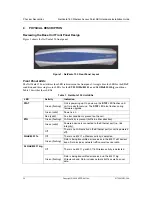
Page 20: ...wer up the STAT LED flashes until unit is ready for service The STAT LED also flashes during firmware upgrade Green solid Power is on Red solid An error condition is present on the unit ETH Green flashing LAN activity is present traffic in either direction Green solid Powered device is connected to the Ethernet port i e link integrity Off There is no LAN activity on the Ethernet port or unit is po...

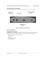
Page 21: ...150 Rear Panel Layout Rear Panel Interfaces 10 100BaseT Ethernet Interface The ETH 0 1 port on the NetVanta 150 is an RJ 45 connector with Power over Ethernet capability See Table A 1 on page 25 for the Ethernet port pinouts The Ethernet port provides the following 10BaseT or 100BaseT with a single connector Auto negotiation CSMA CD IEEE 802 3 compatibility Auto MDI MDIX Reset Switch 10 100 BaseT ...

Page 22: ...wallmount or tabletop configuration The following section provides step by step instructions for wall mounting To prevent electrical shock do not install equipment in a wet location or during a lightning storm Maximum recommended ambient operating temperature is 50 C Instructions for Attaching the Antennas Step Action 1 Place either of the two antennas directly onto the antenna port on the rear pa...

Page 23: ... may not provide sufficient long term stability 3 Install two 8 PAN headscrews 1 1 2 inch or greater in length wood screws into the mounted board following these guidelines and referring to Figure 3 Screws should be spaced horizontally approximately 5 inches apart Find exact positioning by using the location of the two keyed insets on the bottom of the NetVanta 300 Series unit as a guide Screws sh...

Page 24: ... screen appears 6 Click on Getting Started in the System menu on the left side of your screen and follow the on line instructions Factory Default Switch If the factory default switch is pressed during bootup the unit will stay in bootstrap mode Since the unit has no serial port Telnet has been built into the boot code The default IP address is 10 10 10 1 If the factory default switch is pressed an...

Page 25: ...PIN DEFINITIONS The following table provides the pin assignments for the NetVanta 150 Table A 1 10 100BaseT Ethernet Port Pinouts Pin Name Description 1 TX1 Transmit Positive 2 TX2 Transmit Negative 3 RX1 Receive Positive 4 5 Unused 6 RX2 Receive Negative 7 8 Unused ...

Page 26: ...NetVanta 150 Wireless Access Point ABG Hardware Installation Guide 26 Copyright 2006 ADTRAN Inc 61700412E1 34A ...

Page 27: ...erfaces LEDs 21 pinouts 25 F factory default switch 24 features 18 front panel 20 G getting started 24 I installation 22 installing unit 22 interfaces 21 L LEDs 20 M mounting options 22 P passwords page 24 physical description 20 pinouts 10 100BaseT 25 power over ethernet 24 product registration 9 R rear panel 21 S shipping contents 19 specifications 18 U unpacking and inspecting the system 19 W w...

Page 28: ...NetVanta 150 Wireless Access Point ABG Hardware Installation Guide 28 Copyright 2006 ADTRAN Inc 61700412E1 34A ...

Reviews: