

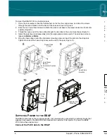


Ground the BSAP
Use the supplied green grounding cable to ground the BSAP 2135 by following these steps:
1. Remove bottom hex head screw from the BSAP unit. This location of the grounding screw is
marked . .. .
2. Place the ground lug of the supplied grounding cable on the shank of the screw and secure the
screw to the unit using an appropriate tool.
3. Attach the other end of the grounding cable to a reliable earth ground point.
C
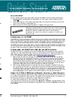
ONNECTING TO THE
BSAP
If the BSAP is to be powered using a network device such as a switch, connect the Ethernet port of the
BSAP to the appropriate switchport. Obtain the IP address of the BSAP from the Dynamic Host Control
Protocol (DHCP) server (based on the MAC address of the BSAP). DHCP is enabled by default. You
can then use a Secure Shell (SSH) client to connect to the BSAP based on the instructions below.
If the BSAP is powered using a PoE injector, connect the Ethernet port of the BSAP to the
OUT
port of
the PoE injector and connect the Ethernet port of the computer to the
IN
port on the PoE injector. Then
proceed to SSH to the default IP address of the BSAP as instructed below.
C
ONFIGURING THE
BSAP
WITH V
WLAN
AND
AP D
ISCOVERY
The BSAP 2135 can be configured for use with the Bluesocket virtual wireless local area network
(vWLAN). If you have installed vWLAN, and want to use AP discovery to configure the BSAP 2135,
follow these steps. For more information on the vWLAN and AP discovery, refer to the
vWLAN AP
Discovery
configuration guide available online at
https://supportforums.adtran.com
.
1. After powering the AP and connecting it to the network, allow the AP to discover the vWLAN
appliance to receive its configuration information. This AP discovery process uses an algorithm
that attempts discovery methods in this order: static configuration, DHCP vendor option (43),
Domain Naming System (DNS) discovery, and cached vWLAN information. If no response to the
discovery request is received, the algorithm moves to the next method in the list (except when
using static configuration, which never queries the other discovery methods).
2. There are two additional network components that can be configured to facilitate AP discovery.
First, an external DHCP server can be configured to assign IP addresses to APs associated with
the vWLAN. When configuring the DHCP server, make sure to configure the Bluesocket DHCP
vendor option (
43
) on the server. Second, you can configure an external DNS server to resolve the
name
apdiscovery
to the IP address of the vWLAN instance in the network environment.
U
SING THE
5 GH
Z
U-NII B
AND IN
E
UROPE
, A
USTRALIA
, N
EW
Z
EALAND
In Europe, Australia and New Zealand the 5 GHz U-NII low band (5150 to 5250 GHz, channels 36, 40,
44, and 48) is designated for indoor use only. If the BSAP 2135 is installed indoors, for example in a
harsh environment such as a warehouse, it must configured for indoor use.
To enable this band/channels for indoor installation, follow these steps:
In the graphical user interface (GUI) navigate to
Configuration
>
Wireless
>
Access Points.
Select
the appropriate access point link to display the configuration menu. Using the
Installed
drop-down list,
select
Indoor
.
Adequate grounding must be provided to the unit. A clearly marked
grounding location is provided on the front of the unit for this
purpose. Consult a certified electrician to ensure that all
grounding and cabling is installed in compliance with the local
electrical code.
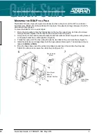
M
OUNTING THE
BSAP
TO AN
E
XTERIOR
C
EILING OR
W
ALL
BSAPs can be mounted in exterior applications or interior applications in harsh environments with an
operating temperature range of -40°F to 131°F (-40°C to 55°C). BSAPs should be positioned for
maximum throughput and range between other APs and wireless client devices. Follow these
instructions to mount the BSAP 2135 to a ceiling or wall:
1. On a flat mounting surface, mark the locations of the four mounting holes using the plane bracket as
a template (Figure 1).
2. Drill an 8 mm diameter hole with a depth of 36 to 38 mm into each of the markings (Figure 2).
3. Hammer the expanding bolts into each of the drilled holes (Figure 3).
4. Place the lock washers, then the flat washers on the four hex cap screws, and drive the screws
through the plane bracket into the back of the case (Figure 4).
5. Install the antennas (sold separately) onto the appropriate antenna ports. The antenna ports are
labeled
2.4GHz
and
5GHz
.
6. Insert the expansion bolts extending from the mounting surface through the holes in the plane
bracket, place the flat washers on the bolts, thread the nuts onto the bolts, and tighten to secure the
bracket to the mounting surface (Figure 5).
Plane Bracket
Expansion Bolts
1
2
3
4
5
Mount Unit on
Expansion Bolts
Mount Plane Bracket
to Unit
Hex Cap Screw
Expansion Bolt
2
Support - Phone: 888-423-8726
Quick Start Guide, 61700962F1-13B, May 2015
7


