


Quick Start Guide, 61700954F1-13B, February 2013
1
4
Copyright © 2013 ADTRAN, Inc. All Rights Reserved.
B
LUESOCKET
1920/1925 A
CCESS
P
OINT
P/N 1700954F1, 1700955F1
H
ARDWARE
Make sure the following items were included in the shipment:
•
Bluesocket 1920/1925 Access Point (BSAP)
•
One plastic wall/ceiling mounting bracket with hardware (two metal screw anchors, two long
screws, two short screws)
•
One flush/recessed ceiling T-rail mounting hardware kit (four T-rail clips (two sizes), two spacers,
two long screws, two short screws)
A
NTENNAS
The BSAP 1920 provides one integrated, four element high-efficiency Planar Inverted F Antenna (PIFA)
array with 3 dBi gain (no external antennas are required). The BSAP 1925 provides four reverse-polarity
subminiature version A (RP-SMA) antenna connectors (no integrated antennas are included with this
model). Two antenna connectors are labeled
2.4G
and two
5G
. These antennas/connectors support two
internal 802.11 radios: one 2.4 GHz 802.11b/g/n radio, and one 5 GHz 802.11a/n radio. Four modular
high-efficiency omnidirectional antennas with 3 dBi gain can be purchased separately for the BSAP
1925 (two 2.4 GHz and two 5 GHz, ADTRAN P/N 1700932F1).
M
OUNTING THE
BSAP
TO A
C
EILING OR
W
ALL
BSAPs should be positioned for maximum throughput and range between other APs and wireless client
devices. Follow these instructions to mount the BSAP to an interior ceiling or wall using the enclosed
ceiling/wall mounting kit:
1. BSAP 1925 only: Install the antennas (sold separately) onto the appropriate antenna ports. The
antenna ports are labeled
2.4G
and
5G
.
2. Using the plastic mounting bracket as a template, mark the location to insert the screw anchors.
3. Press the point of the screw anchors into the sheetrock at the marks and drive them into the wall
using a Phillips-head screwdriver.
4. Insert the long screws through the recessed holes in the plastic mounting bracket and drive them
into the metal anchors.
5. Drive the short screws into the metal screw receptacles on the bottom of the BSAP until they are
firmly seated in the receptacle. If extra space is required, use the spacers and long screws provided
Make a note of the 12-character MAC address and serial number listed on the
back of the BSAP 1920/1925 before mounting the BSAP to a wall or other
surface. This information will be required during configuration.
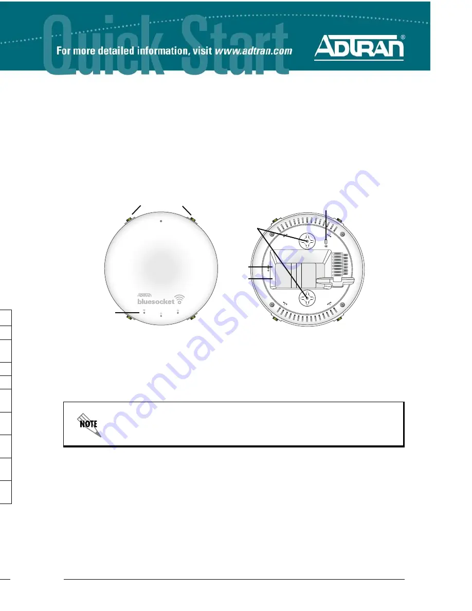
Ethernet
12V DC
LEDs
Antenna Connectors
BSAP 1925 only
Kensington Security
Slot
Optional
12 VDC
Power Port
Ethernet
Port
Mounting Screw
Receptacles
C
ONFIGURING THE
BSAP’
S
IP A
DDRESS
U
SING THE
CLI
By default, DHCP is enabled on the BSAP 1920/1925. If you need to statically configure the IP address
for the BSAP, or statically configure AP discovery, follow these steps:
1. Ensure that the BSAP is connected to the network or a computer and powered as indicated in
Connecting to the BSAP
. If the BSAP is connected to the network, obtain the IP address of the
BSAP from the DHCP server (based on the MAC address of the BSAP).
2. If the BSAP is connected to a computer, specify that the computer’s TCP/IP setting is
On
or
Enabled
by navigating to
Control Panel
>
Network Connections
and double-clicking the
connection of your network interface card. Select
Internet Protocol (TCP/IP)
and select
Properties
. Then specify that the TCP/IP setting is enabled. If the BSAP is connected to the
network, connect your computer to the same network.
3. If the BSAP is connected to a computer, set your PC to a static IP address of
192.168.190.2
with a
subnet mask of
255.255.255.0
. If the BSAP is connected to the network, configure your PC to a
static IP address in the same network (or obtain an IP address using DHCP).
4. Next, access the BSAP’s command line interface (CLI) using an SSH client. Open an SSH
connection using the unit’s default IP address (
192.168.190.1
), or the IP address obtained from the
DHCP server (if connected to the network), and port 2335. To access the unit using vWLAN, and for
more instructions about CLI configuration, refer to the
Bluesocket vWLAN Administrator’s Guide
,
available online at
https://supportforums.adtran.com
.
C
ONFIGURING THE
A
PPLICATION
More detailed documentation for configuring the BSAP 1920/1925 is provided in the
vWLAN
Administrator’s Guide
, available online at
https://supportforums.adtran.com
.
BSAP 1920/1925 LED D
ESCRIPTION
BSAP State
Status
Ethernet
Radio
Boot Loader Initialization
Off
Off
Solid Orange
Operating System
Initialization
Solid Green
Off
Off
LAN Initialization
Flashing Green
Flashing Orange
Off
Discovering vWLAN
Flashing Green
Flashing Green
Off
Firmware Upgrade
(download)
Flashing Orange (Slow)
Flashing Green
N/A
Firmware Upgrade
(writing or verifying)
Flashing Orange (Fast)
Flashing Green
N/A
Firmware Upgrade
Complete
Solid Orange
Flashing Green
N/A
Operational with No
Activity on Radios
Solid Green
Flashing Green
Solid Green
Operational with Activity
on Radios
Solid Green
Flashing Green
Flashing Green


