ADTRAN 17101564F1 Quick Start Manual Download Page 3

617101564F1-13A

3

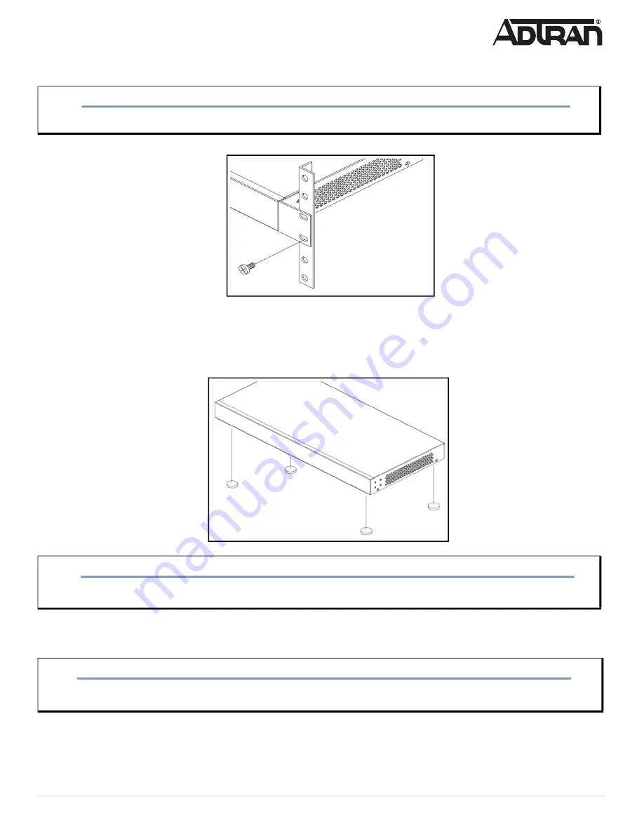
3. Have an assistant hold the unit in position, with the oval holes in the brackets aligned with the mounting holes in the rack posts, as you insert two 

rack screws and tighten them with the appropriate screw driver. 

Figure 4. Attaching Brackets to the Rack Post

Mounting on a Desk or Shelf

To mount the switch on a desk or shelf, complete the following steps.

1. Verify that the desk or shelf is sturdy enough to support the switch. 
2. Attach the four adhesive rubber feet to the bottom of the switch.

Figure 5. Attaching the Rubber Feet

Mounting on a Wall

To mount the switch on a wall, complete the following steps.

1. Using the mounting holes on the bottom of the unit as a template, install four #8 PAN head screws (0.75-inch), using two for each bracket as shown 

in 

Figure 6

, in the appropriate location on the wall. Be aware of the dimensional limitations of the screws. 

2. Slide the keyed insets on the bottom of the unit’s chassis securely onto the screws.

NOTE

g

Rack mount brackets are a default accessory with the unit; spare brackets can be ordered through ADTRAN, part number: 1700519F1.

CAUTION!

f

Desk, shelf, or wall mounting of the equipment should be such that the amount of air flow required for safe operation of the equipment is not 

compromised. Allow 1-inch clearance on the top and sides of the unit for sufficient air flow.

WARNING!

f

Read all the wall mounting instructions carefully before installation. Failure to use the correct hardware, or to follow the correct procedures, 

could result in a hazardous situation for people and damage to the system.

Summary of Contents for 17101564F1

Page 1: ...efore installing or servicing this equipment NetVanta 1560 24 SYSTEM CONSOLE USB RESET 1 2 3 4 5 6 7 8 9 10 11 12 13 14 15 16 17 18 19 20 21 22 23 24 25 26 SYS LED CONSOLE Port 10 100 1000 2500 RJ 45...

Page 2: ...them with a screwdriver to secure the brackets Figure 3 Attaching Brackets to the Switch 2 Position the chassis in the stationary equipment rack Allow 1 inch of clearance between units NOTE g Refer t...

Page 3: ...a template install four 8 PAN head screws 0 75 inch using two for each bracket as shown in Figure 6 in the appropriate location on the wall Be aware of the dimensional limitations of the screws 2 Slid...

Page 4: ...equipment and must be easily accessible 3 Confirm that the power is connected properly The SYSTEM LED should be ON see SYSTEM Status LED Figure 7 Connecting the AC Power Cord CAUTION f The NetVanta 15...

Page 5: ...AC Surge Protection Device be installed at the AC input connection to the local AC Powered product The Surge Protection device should provide L N L G and N G protection It is also recommended that th...

Page 6: ...IP address 3 Power up the switch to be initially configured and wait until it has finished its start up processes 4 Connect the PC to any port on the switch using a standard Ethernet cable and check t...

Page 7: ...atus LEDs The Port Status LEDs indicate the current status of each port NOTE g There are many terminal emulation applications available on the web PuTTY SecureCRT and HyperTerminal are a few examples...

Page 8: ...tore to Factory Defaults 7 12 seconds Flashing Green All LEDs are ON Symptoms Possible Causes Suggested Solutions System LED is OFF The switch is not receiving power 1 Check if correct power cord is c...

Page 9: ...g or maintaining always place devices on an approved antistatic mat that is electrically grounded Warranty ADTRAN will replace or repair this product within the warranty period if it does not meet its...

Reviews: