background image

NetVanta 160 Series

 Unit Installation

61700416F1-34A

Copyright © 2013 ADTRAN, Inc.

23

Mounting the AP to a Dropped Ceiling

The NetVanta 160/161 AP is shipped with a metal ceiling mounting kit to mount the AP on the ceiling tile 
separators of standard dropped ceilings. The plastic mounting bracket can be used to mount the AP to a drywall 
ceiling or ceiling electrical box. Refer to 

Mounting the AP on a Desktop on page 21

 for instructions. NetVanta 

APs should be positioned for maximum throughput and range between other APs and wireless client devices. 
Follow these instructions to mount the AP to a dropped ceiling: 

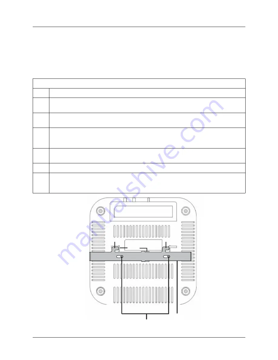
Figure 4.  Attaching the Metal Slider to the AP

Mounting the AP to a Dropped Ceiling

Step

Action

1

For the NetVanta 161 only: Install the antennas (sold separately) onto an appropriate antenna 
port on the AP. The antenna ports are labeled 

2.4G 1

 through 

or 

5G 1

 through 

3

.

2

Using the thumb screws only, carefully thread the antenna onto the appropriate connector until it 
is secure. Repeat Steps 1 and 2 with the each antenna.

3

Lay the metal slider on the back of the AP in the orientation shown in 

Figure 4 on page 23

. Attach 

the slider to the back of the AP using the two small screws provided. After the screws are 
tightened, the slider should slide back and forth clicking into each position.

4

In a suitable location away from obstructions, slide the tabs on the metal ceiling bracket over one 
edge of a ceiling tile separator as shown in 

Figure 5 on page 24

.

5

Slide the moveable section into place and tighten the screw to secure it.

6

Position the AP so that the two tabs on the ceiling bracket locate in the slots in the AP (

A

). Push 

the slider mounted on the AP across until it snaps, locking the AP to the bracket (

B

) as shown in 

Figure 6 on page 24

.

Metal Slider

Slots

Tab

Tab

Metal Slider

Summary of Contents for 160 series

Page 1: ...s Access Point Hardware Installation Guide 1700416F1 NetVanta 160 1700417F1 NetVanta 161 1700922F1 Optional External DC Power Adapter 1700939F1 Optional Set of Six Antennas three 2 4 GHz three 5 GHz 6...

Page 2: ...ion Software Licensing Agreement Each ADTRAN product contains a single license for ADTRAN supplied software Pursuant to the Licensing Agreement you may a use the software on the purchased ADTRAN devic...

Page 3: ...ht 2013 ADTRAN Inc 3 Conventions Notes provide additional useful information Cautions signify information that could prevent service interruption or damage to equipment Warnings provide information th...

Page 4: ...e equipment and shall be easily accessible If any of the following conditions occur unplug the product from the electrical outlet and replace the part or contact your qualified service personnel 1 The...

Page 5: ...y Notice Any changes or modifications not expressly approved by the party responsible for compliance could void the user s authority to operate this equipment This device and its antenna s must not be...

Page 6: ...evice may not cause interference and 2 this device must accept any interference including interference that may cause undesired operation of the device Le pr sent appareil est conforme aux CNR d Indus...

Page 7: ...R UNAUTHORIZED ILLEGAL OR IMPROPER USE OF ADTRAN EQUIPMENT OR SOFTWARE THEREFORE ADTRAN IS NOT LIABLE FOR ANY LOSSES OR DAMAGES RESULTING FROM SUCH FRAUD ATTACK OR IMPROPER USE INCLUDING BUT NOT LIMIT...

Page 8: ...Service and Warranty NetVanta 160 Series 8 Copyright 2013 ADTRAN Inc 61700416F1 34A...

Page 9: ...arize Yourself with the AP Hardware 18 Ethernet LAN Port 18 Power over Ethernet 19 Reset Switch 19 Kensington Security Slot 19 Front Panel LEDs 19 Unit Installation 20 Mounting Options 20 Selecting an...

Page 10: ...Table of Contents NetVanta 160 Series 10 Copyright 2013 ADTRAN Inc 61700416F1 34A...

Page 11: ...and Plastic Mounting Bracket 18 Figure 2 Attaching the Vertical Stand 21 Figure 3 Plastic Mounting Bracket 22 Figure 4 Attaching the Metal Slider to the AP 23 Figure 5 Securing the Metal Ceiling Brac...

Page 12: ...List of Figures NetVanta 160 Series 12 Copyright 2013 ADTRAN Inc 61700416F1 34A...

Page 13: ...ght 2013 ADTRAN Inc 13 List of Tables Table 1 NetVanta 160 161 Antenna Specifications 6 Table 1 Status and Radio LED Definitions 19 Table 2 Network LED Definitions 19 Table A 1 1000Base T Gigabit Ethe...

Page 14: ...List of Tables NetVanta 160 Series 14 Copyright 2013 ADTRAN Inc 61700416F1 34A...

Page 15: ...d connecting to the AP refer to the following sections Mounting Options on page 20 Supplying Power to the AP on page 25 Connecting to the AP on page 25 For information on switch configuration for a sp...

Page 16: ...res of the NetVanta 160 Series AP Features Power from a Power over Ethernet PoE enabled RJ 45 Ethernet connection or from an ADTRAN external 12 VDC converter supply IEEE 802 11a 802 11b 802 11g and 80...

Page 17: ...C to 45 C Humidity Up to 90 percent noncondensing NetVanta 160 Series Shipping Contents Each NetVanta 160 Series unit is shipped in its own cardboard shipping carton Open each carton carefully and av...

Page 18: ...e IEEE 802 3 or 802 3u specifications See Table A 1 on page 27 for Ethernet port pinouts This connector uses an MDI i e internal straight through pin configuration You can use straight through twisted...

Page 19: ...of the unit labeled RESET Press the RESET switch once to reboot the unit Kensington Security Slot The AP includes a Kensington security slot on the side panel You can prevent unauthorized removal of t...

Page 20: ...span power inserters are recommended If building blueprints or floor plans are available use them to define potential client device locations and likely roaming areas Identify possible obstacles or so...

Page 21: ...g the AP on a Table or Shelf Step Action 1 Optional For greater stability drill holes in the table or shelf using the holes in the plastic mounting bracket as a template See Figure 2 on page 21 for a...

Page 22: ...orts are labeled 2 4G 1 through 3 or 5G 1 through 3 2 Using the thumb screws only carefully thread the antenna onto the appropriate connector until it is secure Repeat Steps 1 and 2 with the each ante...

Page 23: ...a port on the AP The antenna ports are labeled 2 4G 1 through 3 or 5G 1 through 3 2 Using the thumb screws only carefully thread the antenna onto the appropriate connector until it is secure Repeat St...

Page 24: ...ght 2013 ADTRAN Inc 61700416F1 34A Figure 5 Securing the Metal Ceiling Bracket to the Ceiling Tile Separator Figure 6 Attaching the AP to the Ceiling Bracket Screw Shown from Above Moveable Section Ce...

Page 25: ...Ethernet port of the AC or to an Ethernet port on a unit that can be accessed by the AC Connect the RJ 45 Ethernet connector on the AP s back panel labeled LAN to your network using a CAT 5 Ethernet c...

Page 26: ...Unit Installation NetVanta 160 Series 26 Copyright 2013 ADTRAN Inc 61700416F1 34A...

Page 27: ...160 Series Table A 1 1000Base T Gigabit Ethernet Port Pinouts Pin Name Description 1 TRD0 Transmit Receive Positive 2 TRD0 Transmit Receive Negative 3 TRD1 Transmit Receive Positive 4 TRD2 Transmit Re...

Page 28: ...NetVanta 160 Series 28 Copyright 2013 ADTRAN Inc 61700416F1 34A...

Reviews: