61200410L1-1B
ESU LT User Manual
29
Chapter 3
Operation
FRONT PANEL OVERVIEW
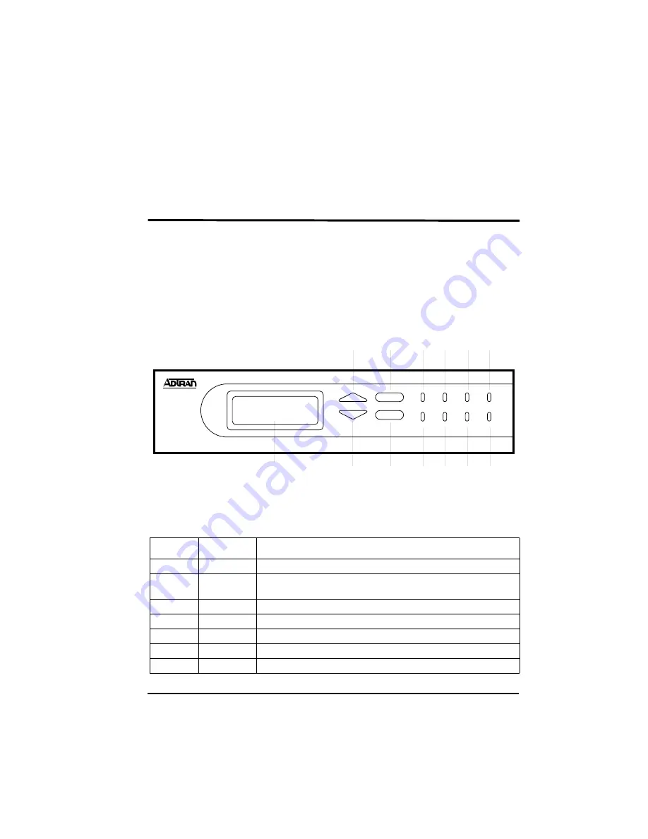
The ESU LT front panel monitors operation and controls the
configuration of the unit. Figure 3-1 shows the ESU LT front
panel. Table 3-1 describes each part of the front panel. Front
panel operation is more fully described in subsequent pages.
Figure 3-1. Front Panel Layout
ESU LT
CS
TEST
ALM
TD
PWR
ERR
RD
RS
ENTER
CANCEL
1
2
3
4
5 6 7 8
9
10
12
11
13
Table 3-1. Front Panel Descriptions
Item
Name
Description
1
PWR
LED ON when power is received by ESU LT.
2
ERR
LED ON when errors such as BPV, CRC-4, FAS word or E-bit errors
have occurred in the last second.
3
ALM
LED ON when an alarm condition exists.
4
TEST
LED ON when unit is in test mode.
5
TD
LED ON when DTE data is being transmitted.
6
RD
LED ON when DTE data is being received.
7
RS
LED ON when request to send (RTS) active from DTE.
Summary of Contents for 1200410L1
Page 1: ...ESU LT User Manual Part Number 1200410L1 61200410L1 1B February 2003 ...
Page 12: ...Table of Contents 12 ESU LT User Manual 61200410L1 1B ...
Page 14: ...List of Figures 14 ESU LT User Manual 61200410L1 1B ...
Page 16: ...List of Tables 16 ESU LT User Manual 61200410L1 1B ...
Page 20: ...Chapter 1 Introduction 20 ESU LT User Manual 61200410L1 1B ...
Page 28: ...Chapter 2 Installation 28 ESU LT User Manual 61200410L1 1B ...
Page 34: ...Chapter 3 Operation 34 ESU LT User Manual 61200410L1 1B ...
Page 40: ...Chapter 4 Status Menu 40 ESU LT User Manual 61200410L1 1B ...
Page 64: ...Chapter 7 Test Menu 64 ESU LT User Manual 61200410L1 1B ...
Page 79: ...Index 61200410L1 1B ESU LT User Manual 79 W wiring 69 ...


