


Hybrid Standalone DVR User Guide
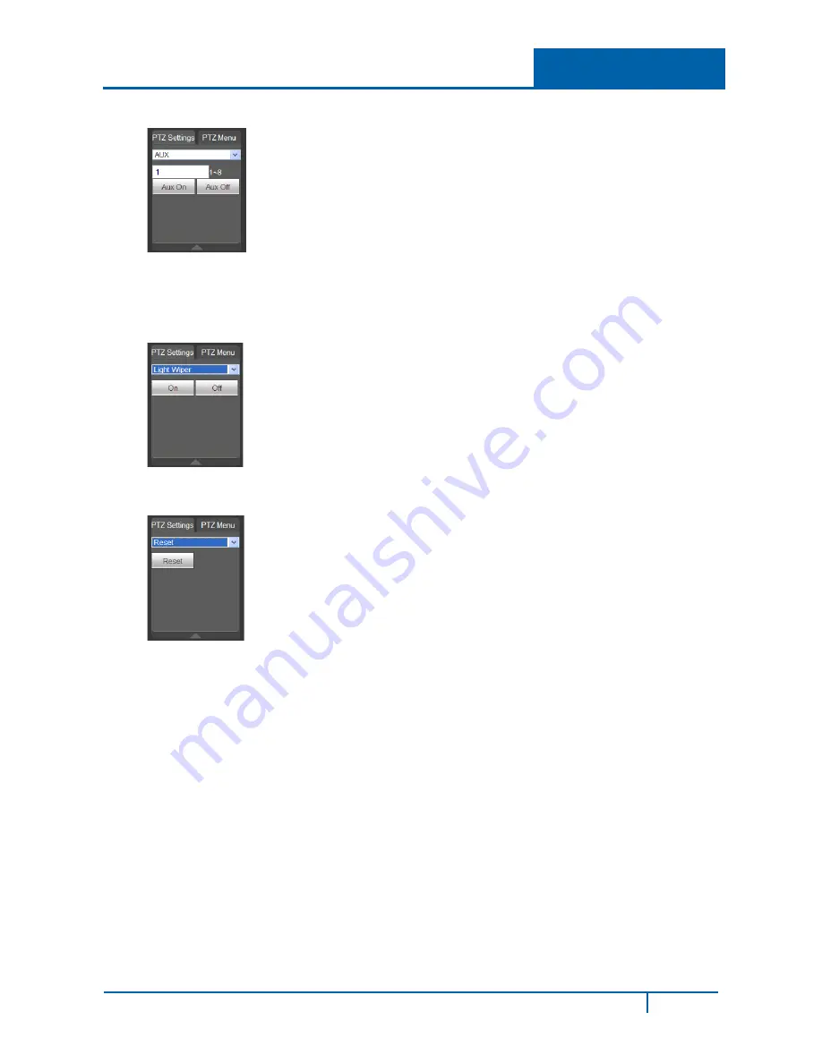
Aux
1.
Input the corresponding aux value, 1-8.
2.
You can select one option.
3.
Click the
Aux On
or
Aux Off
buttons.
Light / Wiper
1.
Turn on or turn off the light/wiper.
Reset
1.
Click the
Reset
button to return PTZ settings to the factory defaults.
DVR7800S-U Series Hybrid DVR User Guide
154