background image

RC8326 Wireless Indoor Day/Night HD Camera Installation Guide


Chapter 2


Basic Setup 

This section provides information on how to assemble and configure the 
RC8326 HD Camera for enrollment. 

Installation  

1.  Assemble the Camera 

Temporarily locate the camera close to the enrollment computer and 
attach the Camera Stand to the camera. 

2.  Power Up 

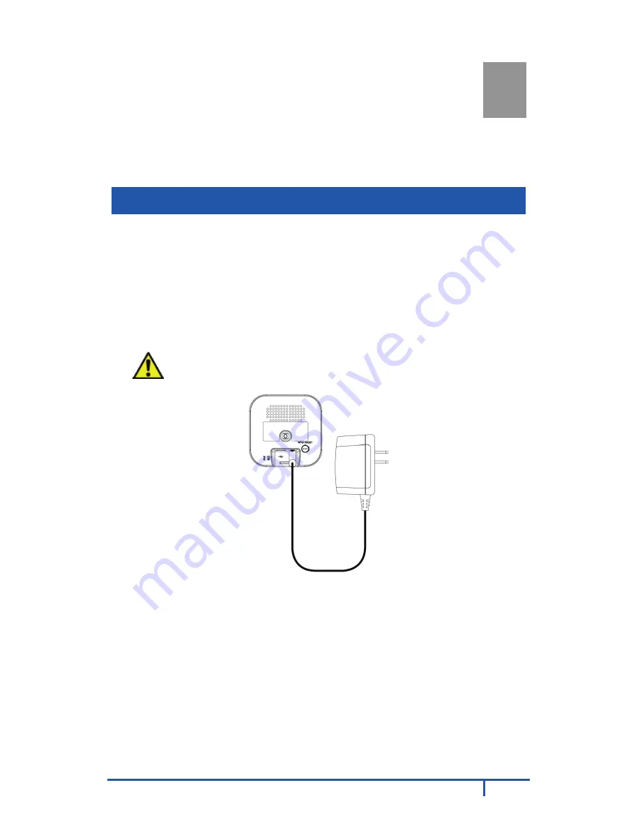
Connect the supplied 12V power adapter to the camera and power up. 
Use only the power adapter provided. Using a different one may cause 
hardware damage. 


CAUTION:

 Use only the power adapter provided. Using a 

different one can result in hardware damage. 


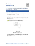
Figure 4: Power Connection 

The Power LED lights up solid green during startup, which takes about 
one minute. After startup is completed, and prior to enrollment, the 
Power LED blinks green. 


Summary of Contents for RC8326

Page 1: ...ADT Pulse Interactive Solutions RC8326 Wireless Indoor Day Night HD Camera Quick Installation Guide ...

Page 2: ...mera Continually Goes Offline 14 CHAPTER 4 WALL MOUNTING 15 APPENDIX A SPECIFICATIONS 17 RC8326 Wireless Day Night HD Camera 17 Regulatory Approvals 18 Property of ADT LLC Information accurate as of published date and is provided as is without warranty of any kind 2017 ADT LLC dba ADT Security Services All rights reserved ADT the ADT logo 800 ADT ASAP and the product service names listed in this d...

Page 3: ...n The wireless HD camera is a standalone system with built in CPU and video encoder It requires only a power source and a connection to the ADT Pulse gateway Dual Video Support The RC8326 supports H 264 and MJEPG video compression Wireless Features Supports 802 11n Wireless Standard The 802 11n standard provides backward compatibility with the 802 11b and g standards Supports WPS Wi Fi Protected S...

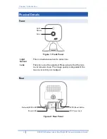
Page 4: ...e 1 Front Panel Light Sensor This is a hardware sensor to detect lux Lens The lens cannot be adjusted Please ensure that the lens cover remains clean The image quality is degraded if the lens cover is dirty or smudged Rear Figure 2 Rear Panel Light Sensor Lens WPS Reset Button Network WPS LED DC Power Jack Power LED ...

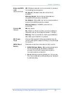
Page 5: ...g Power LED Green Off No power On Power on Power on Also prior to enrollment indicates start up mode approximately 1 minute Blinking Prior to enrollment the Power LED blinks after start up to indicate no network DC Power Input Connect the supplied 12V power adapter here Do not use other power adapters doing so may damage the camera WPS Reset Button This button serves two functions on the camera WP...

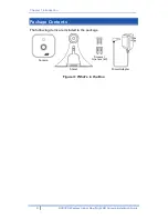
Page 6: ...ntroduction 6 RC8326 Wireless Indoor Day Night HD Camera Installation Guide Package Contents The following items are included in the package Figure 3 What s in the Box Camera Stand Screws Anchors x2 Power Adapter ...

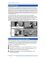
Page 7: ...r and attach the Camera Stand to the camera 2 Power Up Connect the supplied 12V power adapter to the camera and power up Use only the power adapter provided Using a different one may cause hardware damage CAUTION Use only the power adapter provided Using a different one can result in hardware damage Figure 4 Power Connection The Power LED lights up solid green during startup which takes about one ...

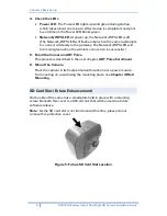
Page 8: ...rn solid green when the wireless connection is successful 5 Enroll the Camera in ADT Pulse This process is described in the next chapter ADT Pulse Enrollment 6 Mount the Camera Place the camera in its final permanent location near a power source For mounting on a wall using the mounting plate see Chapter 4 Wall Mounting SD Card Slot Future Enhancement On the side of the camera is a small plate hel...

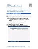
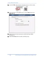
Page 9: ...T Pulse Portal or TS Installer App Using WPS with PIN to Enroll the Camera 1 Set up the camera as described in Chapter 2 2 Launch an Internet browser and log in to the Pulse portal or TS installer app 3 Enter the Manage Devices screen using one of these methods For the Pulse portal select the System tab and click Manage Devices For the TS installer app click the Pulse Devices link The Manage Devic...

Page 10: ...Guide 6 Locate the PIN number located on the label on the rear of the camera 7 On the Add Camera Using WPS screen enter the PIN number in the WPS PIN field 8 Ensure that the camera is powered on and that the Power LED is flashing green 9 Click the Continue button to initiate the WPS process ...

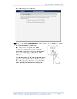
Page 11: ... for 5 seconds to establish a wireless connection Note You must complete the WPS connection within 2 minutes or else the process will time out The time remaining is displayed in the upper left portion of the screen The Network WPS LED flashes amber as the gateway attempts to connect to the camera The wireless connection is successful when the Network WPS LED turns solid green ...

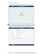
Page 12: ...nstallation Guide The following screen is displayed while the camera is configured 11 When the Camera Details screen appears showing that the camera has been enrolled assign the RC8326 a unique name usually based on the location of the camera in the Name field and then click Save ...

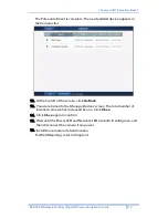
Page 13: ...t the top left of the screen click Go Back 13 You are returned to the Manage Devices screen The total number of installed cameras has increased by one Click Close 14 Click Close again to confirm 15 Wait until the Power LED and Network LED are both lit solid green and then disconnect the camera from power 16 Install the camera in its final location For Wall Mounting refer to Chapter 4 ...

Page 14: ...d object such as tabletop or side wall If installing on a tabletop place the camera as close to the edge as possible as demonstrated in the photos in row 1 below If installing on a wall angle the camera so that a minimal portion of the wall is visible as demonstrated in the photos in row 2 below If the Camera Continually Goes Offline If after enrolling it the camera it continually goes offline Pow...

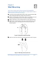
Page 15: ...ng plate forward to release it from the stand 2 Hold the mounting plate at the location where you would like to mount the camera and mark the location of the two mounting holes 3 Drill two pilot holes on the mounting surface at the marked locations 4 Align the two mounting holes on the camera stand with the two pilot holes and mount the mounting plate to the surface using the two screws supplied F...

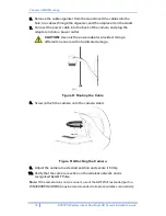
Page 16: ... a power outlet CAUTION Use only the power adapter provided Using a different one can result in hardware damage Figure 8 Routing the Cable 8 Screw attach the camera onto the camera stand Figure 9 Attaching the Camera 9 Adjust the camera to a desired position and secure it firmly 10 Verify that the camera is active on the wireless network and is recognized by ADT Pulse Note If the camera does not r...

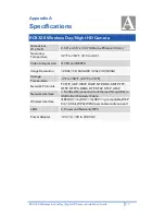
Page 17: ... MJPEG Image Resolution 1280x 720 640x480 320x 240 QVGA Storage Temperature 4 F to 158 F 20 C to 70 C Network Protocols TCP IP UDP ICMP DHCP NTP DNS SMTP FTP HTTP HTTPS DDNS RTP RTSP RTCP UPnP Network Interface 1 RJ 45 LAN connection for Ethernet through Micro USB to RJ 45 Adapter Cable Wireless Interface IEEE 802 11n 802 11b 802 11g compatible WEP 64 128 bit WPA WPA2 personal security support LED...

Page 18: ...eters between the radiator and your body This device complies with Part 15 of the FCC Rules Operation is subject to the following two conditions 1 This device may not cause harmful interference and 2 This device must accept any interference received including interference that may cause undesired operation This transmitter must not be co located or operating in conjunction with any other antenna o...

Reviews: