Models 08, 12, & 20 with 120 V Supply Voltage
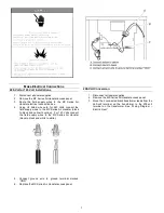
1. Disconnect all power supplies.
2. Remove the air handler access panel.
3. Locate the blue wire (Med) running from the
blower motor to the control board.
4. Remove this blue wire from the control board and
cover this loose end of this wire now with an
insulating cap.
5. Locate the Red or Black wires connected to the
blower motor. Connect the Red (Low) to the
control board at its respective terminal for low
speed or connect the Black (High) to the control
board at its respective terminal for high speed.
6. Replace all panels.
7. Reconnect power.
Model 16 with 120 V Supply Voltage
1. Disconnect all power supplies.
2. Remove the air handler access panel.
3. Locate the black wire (High) running from the
blower motor to the control board.
4. Remove this black wire from the control board
and cover this loose end of this wire now with an
insulating cap.
5. Locate the Blue or Red wires connected to the
blower motor. Connect the Blue (Med) to the
control board at its respective terminal for
medium speed or connect the Red (Low) to the
control board at its respective terminal for low
speed.
6. Replace all panels.
7. Reconnect power.
Instructions for Field Installed Aquastats - Hot Water Heat
(See Sequence of Operations for Factory Installed Aquastat Instructions)
When selecting the proper relay (drawing below) to attach with an aquastat be sure that the relay is capable of the maximum amp
draw required by the Air Handler. For all external aquastats used in conjunction with this Air Handler please follow the installation
instructions provided per the manufacturer of the aquastat.
15
Summary of Contents for MX Series
Page 20: ......

