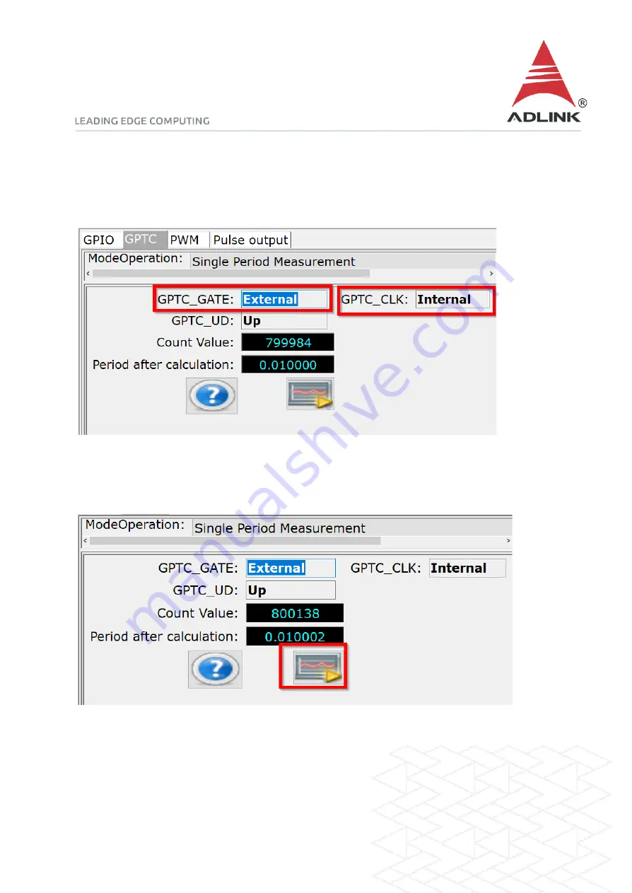
Step 5: Set gate and clock
Set
GPTC_GATE
to External and
GPTC_CLK
to Internal.
Step 6: Run
Press the run button (highlighted below) and the DAQ card will start to measure the period. Thesource signal is 100Hz, the period is 1/100 = 0.01
Page 1: ...the several GPTC functions available to users More information Single period measurement calculates the period of the signal from GPTC_GATE in terms of GPTC_CLK signal The counter calculates the numb...
Page 2: ...the pin definitions to find the GPTC_CLK and GPTC_GATE pin numbers For the USB 1210 the GPTC_CLK is pin 19 and the GPTC_GATE is pin 17 For the USB 1900 series the GPTC_CLK is pin 31 the GPTC_GATE is p...
Page 3: ...Step 2 Connect pins Connect the source signal for measurement to GPTC_GATE pin 17 Step 3 Install U Test Download and install the U Test utility from the ADLINK website...
Page 4: ...ep 4 Launch sample program 1 Launch U test 2 Click Digital Input Output in the left pane 3 Select the GPTC tab in the right pane 4 Under ModeOperation select Single Period Measure or Single Pulse Widt...
Page 5: ...e and clock Set GPTC_GATE to External and GPTC_CLK to Internal Step 6 Run Press the run button highlighted below and the DAQ card will start to measure the period The source signal is 100Hz the period...