
Interfaces
35
Q7-BASE
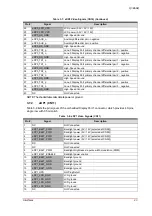
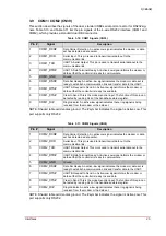
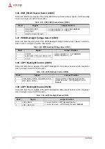
3.29 CAN 5-Volt Enable (CN77)
Table 3-30 lists the pin signals of the CAN 5-Volt Enable jumper header, which provides
2 pins
with 0.079
" (2mm) pitch. The jumper header enables an additional 5 volts and ground for the
CAN header at CN50, pin 9.
NOTE: The shaded table cells denote Ground or Power. Default = open pins, no jumper
installed.
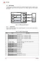
3.30 LPC / TPM Interface (CN78)
Table 3-31 lists the pin signals of the LPC / TPM Interface socket, which provides 20
pins, 2 rows,
with odd/even sequence (1, 2) and 0.100
"
(2.54mm)
pitch.
NOTE: The shaded table cells denote Ground or Power. The # symbol indicates the signal is
Active Low.
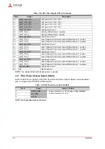
3.31 Fan Voltage Select (CN79)
Table 3-32 lists the pin signals of the Fan Voltage Select jumper header, which provides
3 pins,
single-row, with 0.079
" (2mm) pitch.
NOTE: The shaded table cells denote power or ground. Default = jumper installed on 2-3.
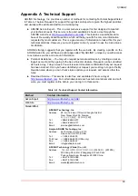
Table 3-30: CAN 5-Volt Enable Signals (CN77)
Pin #
Signal
1
+V5P0_ATX
2
Pin 9 at CN50
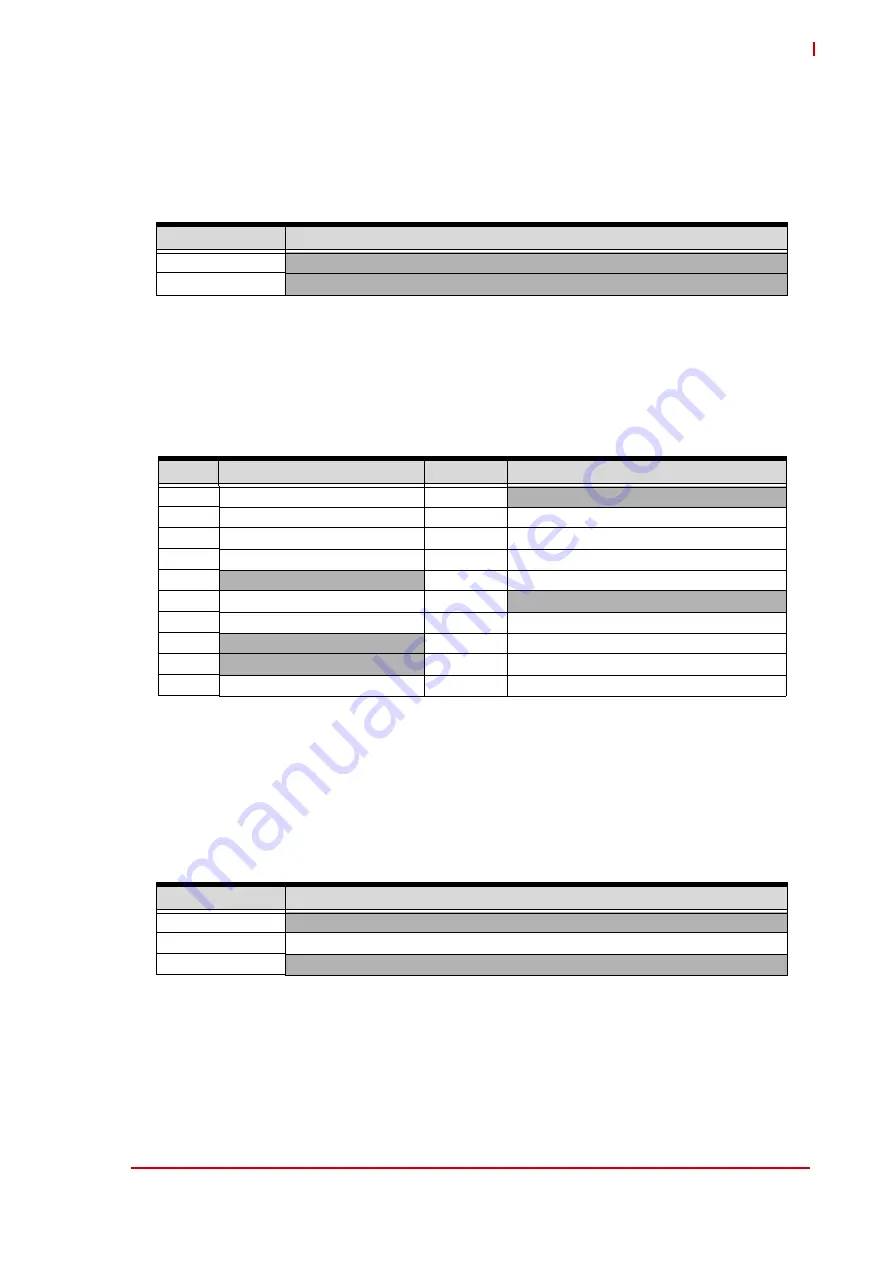
Table 3-31: LPC / TPM Interface Signals (CN78)
Pin #
Signal
Pin #
Signal
1
LPC_CLK
2
GND
3
LPC_FRAME#
4
Removed
5
CB_RESET#
6
Not Connected
7
LPC_AD3
8
LPC_AD2
9
+V3P3_LPC_TPM
10
LPC_AD1
11
GP1WIRE
12
GND
13
Not Connected
14
Not Connected
15
+V3P3_SBY_LPC_TPM
16
LPC_SERIRQ
17
GND
18
Not Connected
19
LPC_PD#
20
Not Connected
Table 3-32: Fan Voltage Select Signals (CN79)
Pin #
Signal
1
+V12P0_ATX
2
FAN_PWR_CN
3
+5V_IN