

Interfaces
21
Q7-BASE
3.5
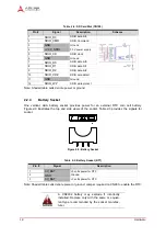
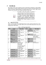
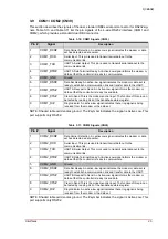
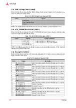
Smart Battery (BattMan) Interface (CN5)
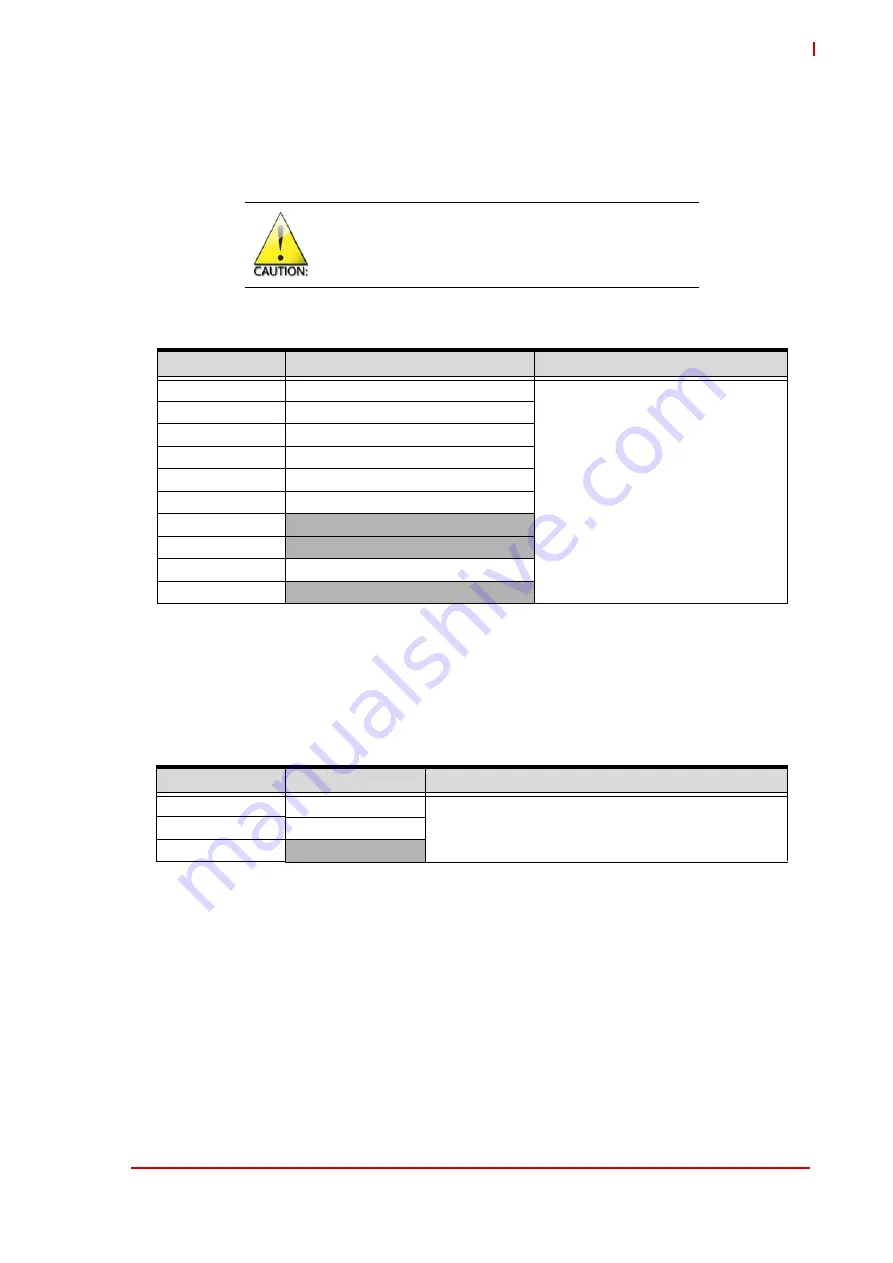
Table 3-5 lists the pin signals of the Smart Battery header, which provides 10 pins in 2 rows,
odd/even pin sequence (1, 2), and 2.54mm pitch.
NOTE: The # symbol indicates the signal is Active Low. Shaded table cells denote power or
ground.
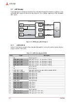
3.6
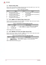
Post Code Enable (CN8)
Table 3-6 lists the pin signals of the Post Code Enable jumper header, which provides 3 pins in a
single row with 0.079" (2.00mm) pitch.
NOTE: The shaded table cells denote ground.
You must configure the jumper settings as
described in Table 3-5, or system damage could
occur when using a BattMan power supply to
Power On the carrier.
Table 3-5: Smart Battery (BattMan) Interface (CN5)
Pin #
Signal
Jumper Settings
1
SMB_CLK_5V (SMBus clock)
Make sure to set the following jumper
configurations before implementing a
BattMan power supply to Power On the
carrier:
• Remove the jumper from the 2-pin
jumper header,
CN3
(5V
Standby)
• Remove the jumper from the 2-pin
jumper header,
CN4
(5V
Power Good)
• Install a jumper on pins 1-2 of the
CN81
jumper header (ATX_PWRGD)
2
SMB_DAT_5V (SMBus data)
3
Not Connected
4
Not Connected
5
ATX_PS_ON# (ATX power supply)
6
Not Connected
7
+V12P0_ATX (12-volt power)
8
+V5P0_SBY (5-volt standby power)
9
SMB_ALERT_5V# (SMBus alert)
10
GND
Table 3-6: Post Code Enable (CN8)
Pin #
Signal
Jumper Position
1
LPC_CLK_POST
• Jumper Installed 1-2 - Post Code enabled (
Default
)
• Jumper Installed 2-3 - Post Code disabled
2
POST_CLK
3
GND