


Product Overview
5
Q7-BASE
1.5.4
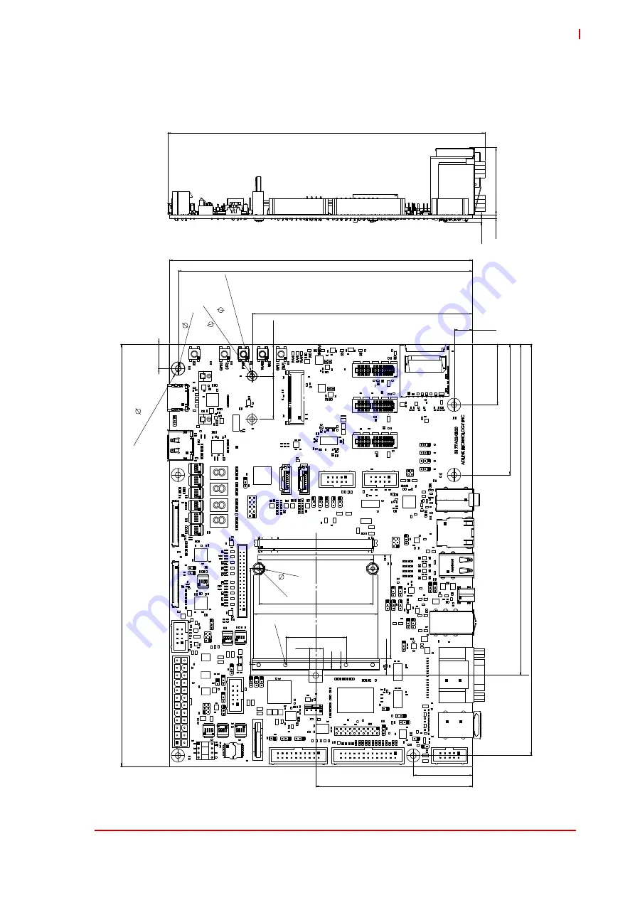
Mechanical
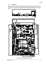
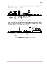
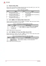
Figure 1-3 provides the mechanical dimensions and mounting hole sizes of the Q7-BASE. The
Q7-BASE can be mounted to a chassis using M4, B-head screws. Mezzanine cards can be
mounted to the carrier using female-female standoffs with M2.5 threads and M2.5, B-head
screws.
Figure 1-3: Mechanical Dimensions (Top Side)
34
2
x
M
2.5
2
x M2.5
2
37.5
2.35
177.97
17.90
73.25
9.42
64.8
170
24.18
33.91
69.72
237
54
165.10
33.02
10.16
6
x
(To
p
a
n
d
Bo
tt
om
)
13.71
230.73
5.
5
2.
7
5
2
x
2
x
7.
5
7.5
3.
2
(To
p
a
nd
Bo
ttom
)
7
x
123.55
5.2
4
64
6
2 x
58.42
87.81
185.88
Q7-BASE R1_B2_Carrier_Mech_Dmn_c
2
2