Introduction • 1
Introduction
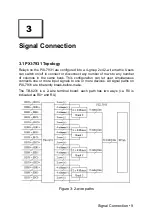
ADLINK PXI-7931 is a matrix module with 32 cross-point 2-wire relays (DPDT,
2 Form C). The default configuration of the PXI-7931 is a 4-group 2x4 2-wire
matrix. With the termination board, TB-6231, users can flexibly choose one of
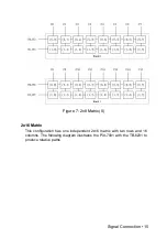
the configurations: one 4x8, two 4x4, one 2x16, two 2x8, and four 2x4. Any
contact of the PXI-7931 can connect to other contacts at the same bank,
individually, or in combination. The PXI-7931 matrix module simplifies wiring
and makes it easy to change the internal connection path.
The contact position of the relays can be changed either by direct software
commands or by following the instructions previously stored in the on-board
scan list. The scan list advances upon the trigger from external measurement
devices, such as a DMM. The scan list can also advance when the scan-delay
timer expires. PXI trigger functions are supported and software programmable.
Multiple modules can be synchronized without additional field wiring.
1.1 Features
•
PXI specifications Rev. 2.0 compliant
•
3U Eurocard form factor, CompactPCI compliant (PICMG 2.0 R3.0)
•
PICMG 2.1 R2.0 CompactPCI Hot-Swap specifications compliant
•
32 DPDT (2 Form C) non-latching relays
•
Contact rating
•
2A switching, 2A carrying
•
220V
DC
, 125V
AC
•
200 operations per second
•
1k-sample scanlist for deterministic scanning
•
Provides handshaking signals to trigger external instruments
•
Programmable emergency shutdown function and Watchdog timer for
safety critical applications
•
Eight auxiliary 3.3 V/TTL digital inputs/outputs with 5V tolerance
•
Supports PXI backplane triggers to synchronize multiple modules
•
Fully software programmable
1
Summary of Contents for PXI-7931
Page 10: ...4 Introduction This page intentionally left blank...
Page 13: ...Installation 7 Figure 2 Installing the switch module into a PXI platform...
Page 14: ...This page intentionally left blank 8 Installation...
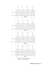
Page 19: ...Signal Connection 13 Figure 5 2x4 Matrix II...


