background image

Getting Started

 13

MIX-220

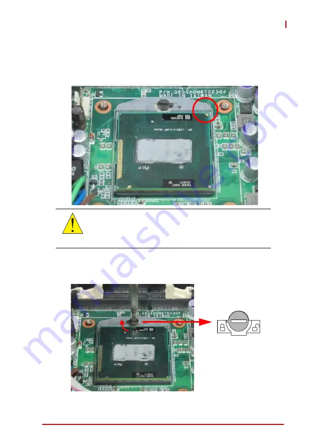
2. Align the gold triangle at the upper-right corner of the

CPU with the triangular mark at the upper-right corner of
the socket. Gently place the CPU into the socket. It
should drop into the socket without having to apply any
downward force.

3. While gently holding the processor down with your fin-

ger, turn the CPU lock screw clockwise to lock the CPU
in place.

CAUTION:

You should not have to press down on the processor. If the 
processor does not drop completely into the socket, make 
sure the CPU lock screw is fully turned to the unlocked 
position.

Summary of Contents for MIX-220

Page 1: ...Advance Technologies Automate the World Manual Rev 2 00 Revision Date June 4 2012 Part No 50 1Z126 1000 MIX 220 Embedded Computer System with MI 220 Mini ITX Motherboard User s Manual ...

Page 2: ...ii Revision History Revision History Revision Release Date Description of Change s 2 00 2012 06 04 Initial release ...

Page 3: ...even if advised of the possibility of such damages Environmental Responsibility ADLINK is committed to fulfill its social responsibility to global environmental preservation through compliance with the Euro pean Union s riction of Hazardous Substances RoHS directive and Waste Electrical and Electronic Equipment WEEE directive Environmental protection is a top priority for ADLINK We have enforced m...

Page 4: ...sage of this document and its associated product s Chapter 1 Introduction Introduces the MIX 220 its features specifications and mechanical dimensions Chapter 2 Getting Started Presents information on chassis lay out setup and operation of the MIX 220 Chapter 3 Hardware Information Provides information about fan removal replacement connectors and pin assignments Important Safety Instructions Prese...

Page 5: ...rly NOTE NOTE Additional information aids and tips that help users perform tasks CAUTION Information to prevent minor physical injury component dam age data loss and or program corruption when trying to com plete a task WARNING Information to prevent serious physical injury component damage data loss and or program corruption when trying to complete a specific task ...

Page 6: ...vi Preface This page intentionally left blank ...

Page 7: ...ng Started 7 2 1 Packing List 7 2 2 Chassis Layout 8 2 3 Installing the CPU 12 2 4 Installing the CPU Cooler 14 2 1 Installing the CPU Cooler 14 2 5 System Memory 15 2 6 SATA Drive Installation 16 2 7 Installing PCIe PCI Cards 20 2 8 Wall Mount Brackets 21 2 9 Powering Up 22 2 10 Driver Installation 23 3 Hardware Information 25 3 1 Fan Removal and Replacement 25 3 2 I O Connector Pin Definitions 2...

Page 8: ...viii Important Safety Instructions 33 Getting Service 35 ...

Page 9: ...X 220 List of Figures Figure 1 1 MIX 220 Dimensions without wall mount brackets 5 Figure 1 2 MIX 220 Dimensions with wall mount brackets 6 Figure 2 1 MIX 220 Front Rear Panel 8 Figure 2 2 MIX 220 Drive Bay and Fan Access 9 ...

Page 10: ...x List of Figures This page intentionally left blank ...

Page 11: ...List of Tables xi MIX 220 List of Tables Table 1 1 MIX 220 General Specifications 4 ...

Page 12: ...xii List of Tables This page intentionally left blank ...

Page 13: ...i7 i5 i3 and Celeron processors Intel QM67 Express chipset and Dual Channel DDR3 1066 1333MHz up to 8GB in two SODIMM slots Features include integrated Intel HD Graphics VGA DVI D HDMI out puts dual Gigabit Ethernet six USB 2 0 ports four serial ports 1x RS 232 422 485 3x RS 232 and an externally accessible anti shock drive bay for two 2 5 SATA 6Gb s drives The MIX 220 provides a PCIe x16 slot and...

Page 14: ...es dependent on CPU model X 2x GbE Intel 82579LM 82574L controllers X 6x USB 2 0 ports 2x front 4x rear X Anti shock drive bay for two 2 5 SATA 6Gb s drives X Four serial ports 1x RS 233 422 485 3x RS 233 X PCIe x16 slot PCI slot PCI Express Mini Card slot X HD audio with Mic Line In Line Out X Dual 6cm fans with air filters X 250W FlexATX AC power supply X Wall mount brackets X Mounting point for...

Page 15: ...ependent on CPU model Ethernet 2x GbE Intel 82579LM 82574L controllers Wake on LAN supported Audio Realtek ALC892 HD audio Watchdog Timer 1 255 second minute programmable Hardware Monitor CPU temperature and supply voltages Operating System Windows XP 7 32 64 bit Fedora 14 Red Hat Enterprise Linux 5 I O Interfaces Front I O 2x USB 2 0 ports Rear I O 2x RJ 45 LAN ports 4x USB 2 0 ports 1x DB 15 VGA...

Page 16: ...s Power Requirements Input 100 240 VAC universal Mode ATX power Mechanical and Environment Dimensions 330 mm x 212 mm x 88 mm W x D x H Operating Temp 0 C to 50 C Storage Temp 20ºC to 75ºC Rel Humidity 10 to 90 non condensing Certifications CE FCC Class A ...

Page 17: ...Introduction 5 MIX 220 1 4 Mechanical Drawing Figure 1 1 MIX 220 Dimensions without wall mount brackets Dimensions in mm 233 2 221 2 87 2 93 6 330 Rear View Top View Le View Right View Front View ...

Page 18: ...6 Introduction Figure 1 2 MIX 220 Dimensions with wall mount brackets Dimensions in mm 140 87 2 92 2 330 360 380 233 2 221 2 180 Rear View Top View Le View Right View Front View ...

Page 19: ...otherboard Quick Reference Guide WARNING DO NOT install or apply power to equipment that is damaged or if there is missing incomplete equipment Retain the ship ping carton and packing materials for inspection Please con tact your ADLINK dealer vendor immediately for assistance Obtain authorization from your dealer before returning any product to ADLINK CAUTION To prevent damage to the system ensur...

Page 20: ...red peripheral devices e g monitor key board mouse LAN to the system Refer to Figure 2 1 below for connector locations Figure 2 1 MIX 220 Front Rear Panel HDD Power LEDs On Off Switch Reset Front Panel USB Rear Panel USB LAN HDMI VGA DVI PCIe slot PCI slot COM1 2 COM3 4 AC in ...

Page 21: ...e bay and cooling fan modules can be accessed from the bottom of the chassis as shown below See SATA Drive Installation on page 16 and Fan Removal and Replacement on page 25 for more information Figure 2 2 MIX 220 Drive Bay and Fan Access Drive Bay Cooling Fans ...

Page 22: ...10 Getting Started Removing the Chassis Cover 1 Remove the two screws indicated below 2 Slide the cover back to release the front edge ...

Page 23: ...Getting Started 11 MIX 220 3 Lift off the cover to access the inside of the chassis ...

Page 24: ... processors in Socket G2 To install the CPU 1 Locate the CPU socket If the socket is locked use a flathead screwdriver to turn the CPU lock screw counter clockwise to the unlocked position WARNING When installing carefully hold the CPU by its edges and do not force the CPU into the socket to avoid bending the pins ...

Page 25: ...socket It should drop into the socket without having to apply any downward force 3 While gently holding the processor down with your fin ger turn the CPU lock screw clockwise to lock the CPU in place CAUTION You should not have to press down on the processor If the processor does not drop completely into the socket make sure the CPU lock screw is fully turned to the unlocked position ...

Page 26: ...ore using the sys tem Failure to install a CPU cooler may damage the mother board and or CPU CPU Fan Connector 2 1 Installing the CPU Cooler To install the CPU cooler 1 The CPU cooler has a layer of thermal grease pre applied If you are reinstalling the CPU apply a new layer of thermal grease evenly to the top of the installed CPU 2 Position the heatsink on top of the installed CPU until the heats...

Page 27: ...IMM sockets To install a memory module 1 Locate the SO DIMM slots on the motherboard 2 Align the memory module on the socket making sure that the notch matches the break on the socket 3 Insert the module firmly into the slot until the retaining clips snap back inwards and the module is securely seated WARNING Disconnect all power supply to the board before installing a memory module to prevent dam...

Page 28: ...16 Getting Started 2 6 SATA Drive Installation 1 Remove the four screws securing the drive bracket to the chassis 2 Lift the drive bracket out of the chassis ...

Page 29: ...220 3 Remove the four screws securing the two sets of SATA signal and power cables to the drive bracket 4 Turn the drive bracket over and locate the mounting screws and shock absorbers in the accessory kit four each per drive ...

Page 30: ... Place the 2 5 SATA drive in the drive bracket with the top side up as shown Check that the connectors on the drive align with the opening in the bracket Secure the drive to the bracket with the mounting screws provided 7 Repeat steps 5 and 6 if you wish to install a second drive SATA Connectors ...

Page 31: ... four screws removed in step 3 9 Place the drive bracket into the chassis and secure it with the four screws removed in step 1 CAUTION Be sure to secure both sets of SATA cables to the drive bracket to prevent them from interfering with cooling fan operation Failure to do so may cause the system to over heat and or damage components ...

Page 32: ... 7 Installing PCIe PCI Cards Remove the chassis cover as described on page 10 The MIX 220 provides one PCIe x16 expansion slot upper and one PCI expan sion slot lower The maximum allowed card length is 190 mm PCIe x16 PCI ...

Page 33: ...kets and mounting screws are provided for the MIX 220 Before installing the brackets remove the four rub ber feet from the bottom of the chassis as indicated below The bracket mounting locations are shown in Figure 1 2 MIX 220 Dimensions with wall mount brackets on page 6 ...

Page 34: ...ower cord to the AC connector on the rear panel of the chassis Plug the AC power cord into a suitable wall outlet Power on any peripheral devices such as a display monitor Press the On Off power switch on the front of the chassis to power on the system ...

Page 35: ...y driver and utilities by running the program X Driver Step 2_VGA winxp32 winxp_14464 exe Follow the instructions given and reboot when instructed 4 Install the LAN driver by running the program X Driver Step 3_LAN XP_32 PROWin32 exe Follow the instructions given and reboot if required 5 Install the Audio driver by running the program X Driver Step 4_AUDIO XP 32_64 WDM_R261 exe Follow the instruct...

Page 36: ...ep 5_RAID Intel_Rapid_Storage_Technology_ 10 6 0 1022 zip Install the Management Engine driver by running the program X Driver Step 6_ME setup exe Follow the instructions given and reboot if required NOTE NOTE The Intel Rapid Storage Technology Utility file may not be included on the Driver CD Please download it from the ADLINK website if necessary ...

Page 37: ...MIX 220 3 Hardware Information 3 1 Fan Removal and Replacement 1 Remove the two screws securing the fan module to the chassis 2 Lift the fan module out of the chassis as shown Cut and remove the cable tie to release the wiring ...

Page 38: ...cable tie to shorten the wiring and secure it towards the center of the chassis as shown to prevent the wiring from interfering with normal fan operation CAUTION Failure to properly secure the wiring may result in improper cooling fan operation causing the system to overheat and or damage to components Center of the Chassis ...

Page 39: ...he module fits into the slots inside the chassis 6 Place the connector into the gap beside the fan to allow it to fit into the chassis 7 Slide the module into the chassis and secure it with the two screws removed in step 1 8 Repeat steps 1 through 7 for the other fan module if required ...

Page 40: ...l Name Red 1 2 Green Blue 3 4 VCC pull up GND 5 6 GND GND 7 8 GND VCC 9 10 GND VCC pull up 11 12 DDC2B DATA HSYNC 13 14 VSYNC DDC2B CLK 15 Pin Signal Pin Signal 1 TMDS Data2 2 TMDS Data2 Shield 3 TMDS Data2 4 TMDS Data1 5 TMDS Data1 Shield 6 TMDS Data1 7 TMDS Data0 8 TMDS Data0 Shield 9 TMDS Data0 10 TMDS Clock 11 TMDS Clock Shield 12 TMDS Clock 13 CEC 14 Reserved 15 SCL 16 SDA 17 DDC CEC Ground 1...

Page 41: ...Data4 20 TMDS Data5 6 DDC Clock 21 TMDS Data5 7 DDC Data 22 TMDS Clock Shield 8 Analog Vertical Sync 23 TMDS Clock 9 TMDS Data1 24 TMDS Clock 10 TMDS Data1 C1 NC 11 TMDS Data1 3 Shield C2 NC 12 TMDS Data3 C3 NC 13 TMDS Data3 C4 NC 14 5 V Power C5 NC 15 GND NOTE NOTE Although the connector has a DVI I type pinout pins C1 through C5 are not connected and VGA signals are NOT supported Pin Signal Name...

Page 42: ...ne Out and Mic In functions The blue Line In jack connects to an audio source such as a CD player The green Line Out port connects to speakers or headphones while the pink Mic In jack connects to a microphone Pin 10BASE T 100BASE TX 1000BASE T 1 TX BI_DA 2 TX BI_DA 3 RX BI_DB 4 BI_DC 5 BI_DC 6 RX BI_DB 7 BI_DD 8 BI_DD LED1 Activity Link LED2 Speed Status Description Status Description Off No Link ...

Page 43: ... RS 422 RS 485 1 DCD L TXD TXD 2 RXD TXD TXD 3 TXD RXD 4 DTR L RXD 5 GND GND GND 6 DSR L 7 RTS L 8 CTS L 9 RI L NOTE NOTE See the MI 220 User s Manual BIOS chapter for COM1 Serial Port Mode settings Pin RS 232 1 DCD L 2 RXD 3 TXD 4 DTR L 5 GND 6 DSR L 7 RTS L 8 CTS L 9 RI L 1 5 6 1 5 6 ...

Page 44: ...32 Hardware Information This page intentionally left blank ...

Page 45: ...Turn off power and unplug any power cords cables X To avoid electrical shock and or damage to equipment Z Keep equipment away from water or liquid sources Z Keep equipment away from high heat or high humidity Z Keep equipment properly ventilated do not block or cover ventilation openings Z Make sure to use recommended voltage and power source settings Z Always install and operate equipment near an...

Page 46: ...viced by authorized technicians when Z The power cord or plug is damaged Z Liquid has penetrated the equipment Z It has been exposed to high humidity moisture Z It is not functioning or does not function according to the user s manual Z It has been dropped and or damaged and or Z It has an obvious sign of breakage WARNING Risk of explosion if battery is replaced with one of an incorrect type Dispo...

Page 47: ...g Chun Rd Zhangjiang Hi Tech Park Pudong New Area Shanghai 201203 China Tel 86 21 5132 8988 Fax 86 21 5132 3588 Email market adlinktech com ADLINK Technology Beijing Address ҀᏖ ऎϞഄϰ䏃 1 োⲜ ࡼ ॺ E ᑻ 801 ᅸ 100085 Rm 801 Power Creative E No 1 B D Shang Di East Rd Beijing 100085 China Tel 86 10 5885 8666 Fax 86 10 5885 8626 Email market adlinktech com ADLINK Technology Shenzhen Address ഇᏖफቅऎ ᡔುफऎ催ᮄफϗ䘧 ᄫ...

Page 48: ...r B D 1675 12 Seocho Dong Seocho Gu Seoul 137 070 Korea Tel 82 2 2057 0565 Fax 82 2 2057 0563 Email korea adlinktech com ADLINK Technology Singapore Pte Ltd Address 84 Genting Lane 07 02A Cityneon Design Centre Singapore 349584 Tel 65 6844 2261 Fax 65 6844 2263 Email singapore adlinktech com ADLINK Technology Singapore Pte Ltd Indian Liaison Office Address 1st Floor 50 56 Between 16th 17th Cross M...

Reviews: