ADLINK Technology MECS-7211 User Manual Download Page 25

Preliminary


25 

MECS-7211 

 
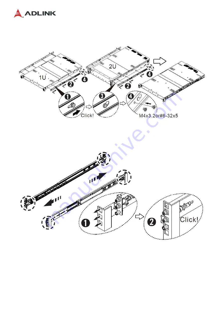
2.  Install the inner rail onto the chassis. 


3.  Attach the outer rail/bracket assembly to the rack. 


Note:

 Front and rear bracket installation procedures are the same. The left and right sides of 

the rail are symmetrical. Repeat the installation steps for the other side. 


Summary of Contents for MECS-7211

Page 1: ...Preliminary MECS 7211 2U Edge Computing Server with Dual Intel Xeon Processor User s Manual Manual Rev Rev 0 3 preliminary Revision Date November 24 2021 Part No 50M 00046 1000...

Page 2: ...social responsibility to global environmental preservation through compliance with the European Union s Restriction of Hazardous Substances RoHS directive and Waste Electrical and Electronic Equipmen...

Page 3: ...es aux composants la perte de donn es et ou la corruption de programme lors de l ex cution d une t che sp cifique AVERTISSEMENT Information to prevent minor physical injury component damage data loss...

Page 4: ...7 3 8 Connecting the System to Ground 30 3 9 System Power Cable Installation 31 3 10 Login to the BMC via Console Port 32 3 11 Login to the BMC via Network 34 3 12 BMC eth0 Default and Static IP Setti...

Page 5: ...b Menu CPU Configuration 65 5 4 2 Sub Menu Memory Configuration 66 5 4 3 Sub Menu Memory Topology 68 5 4 4 Sub Menu UPI Configuration 69 5 4 5 Sub Menu UPI Status 71 5 4 6 Sub Menu Memory Error Enabli...

Page 6: ...Gen3 expansion slots 16x DDR4 memory slots for up to 512GB memory to meet the requirements of network packet processing Up to 4x 2 5 external hot swappable SATA drives and additional storage expansion...

Page 7: ...Preliminary 7 MECS 7211 1 1 Block Diagram...

Page 8: ...l Overview 1 2 1 Front Panel 1 2 2 Rear Panel AC Version DC Version LEDs SATA Drive Bays x4 Console Port VGA RJ45 x2 SFP x4 USB x2 Power Button Reset Button PCIe Expansion Slots x4 PCIe Expansion Slot...

Page 9: ...7211 1 2 3 Chassis Layout See 3 1 Removing the Chassis Cover on page 13 for instructions on removing the cover DDRS DIMM x16 PSU Fans PCIe x16 Gen3 FHFL x2 SATA Drive Bays x4 PCIe x8 Gen3 HHHL x1 Sec...

Page 10: ...Preliminary 10 MECS 7211 1 3 Mechanical Dimensions Units mm 448 454 87 481...

Page 11: ...Server 2016 Linux Kernel 2 6 and above Intel QuickAssist Technology 100Gb s Intel QAT support SKU dependent Trusted Platform Module TPM 1 2 TPM 2 0 optional Chassis Management IPMI v2 0 compliant with...

Page 12: ...g Storage 5 to 90 non condensing Operating half sine 2G 11ms pulse 100 pulses on each of three axes Shock3 Non operating trapezoidal 25G 170 inches sec delta V three drops on each of three axes Vibrat...

Page 13: ...down on the two depressions with your thumbs and slide the cover towards the rear of the chassis large arrows Remove the cover To reinstall the cover slide it towards the front of the chassis then re...

Page 14: ...er the blue DIMM slots are completely filled otherwise the device will not boot up Please refer to the figure below Note The device will not boot up if the black DIMM slots are populated before the bl...

Page 15: ...PCIe x16 Gen3 FHFL single slot passive cooled expansion cards The cards are mounted inside two riser card cover assemblies Two FHFL single slot cards or one FHFL dual slot card can be installed in ea...

Page 16: ...slot on the motherboard which is directly below the handle Carefully lift the riser card cover assembly straight up to remove it from the chassis 3 Turn the riser card cover assembly over and remove...

Page 17: ...O panel of the assembly and insert the PCIe connectors into the PCIe x16 slot on the riser card Make sure the connectors are fully inserted into the PCIe slot 5 Secure the PCIe expansion card to the...

Page 18: ...ssis and riser card edge connectors with the slot on the motherboard Press down until the assembly is securely installed Attach the screw securing the top of the riser card cover assembly and tighten...

Page 19: ...xpansion cards please contact your ADLINK representative Follow the instructions below to install a PCIe x8 Gen3 HHHL single slot passive cooled expansion card 1 To install a PCIe x8 card remove the s...

Page 20: ...Preliminary 20 MECS 7211 2 Insert the PCIe x8 card into the PCIe slot in the motherboard and secure it to the front panel of the chassis with a the screw as shown...

Page 21: ...nnectors to provide secondary power for PCIe x16 cards if required Two break out cables are also included The pin definitions of the connectors and cables are described below 4 pin ATX type 12V Power...

Page 22: ...le Connector Pinout P2 P1 2 1 3 4 6 1 1 2 3 4 P1 1 Pinout 2 3 4 1 2 3 1 4 5 6 P2 2 X All installation procedures are restricted to qualified personnel Toutes les proc dures d installation sont r serv...

Page 23: ...rack post type before proceeding The pre installed rail type is for square hole posts If the rack post has round holes please switch to the appropriate screws as shown below To switch from round hole...

Page 24: ...Preliminary 24 MECS 7211 1 Remove the inner rail...

Page 25: ...r rail onto the chassis 3 Attach the outer rail bracket assembly to the rack Note Front and rear bracket installation procedures are the same The left and right sides of the rail are symmetrical Repea...

Page 26: ...tion Ensure the ball bearing retainer is located at the front of the rail Insert the chassis into the outer rails When the chassis is fully inserted pull push the release tab on the inner rails Secure...

Page 27: ...Preliminary 27 MECS 7211 3 7 Uninstalling the Rails from the Chassis M4 x3 2 or 6 32 x5 Release the latch to detach the inner rail...

Page 28: ...MECS 7211 Detach the outer rail bracket assembly from the rack Note Front and rear bracket detachment procedures are the same The left and right sides of the rail are symmetrical Repeat the steps for...

Page 29: ...Preliminary 29 MECS 7211 Loosen the captive screws and then pull out the chassis Pull release button A or B to remove the chassis...

Page 30: ...ected to ground by the ground pin of the 3 prong IEC power cord Please use the power cord provided with the system for your region A grounding stud M3 size is provided on the rear of the chassis for a...

Page 31: ...nput 3 prong IEC power connector DC PSU Input Use the included cable to connect to the DC power inlet BizLink 115H0 025987 R1 Align the connector on the cable with DC power inlet and secure it with th...

Page 32: ...SW6 on the I O board see 1 2 3 Chassis Layout on page 9 Pin Default BMC Debug 1 OFF ON 2 ON OFF 3 OFF ON 4 ON OFF Step 2 Use the included RJ 45 to DB 9 console port adapter cable to connect the PC to...

Page 33: ...pen a serial port console tool such as PuTTY choose the higher COM port it may be different depending on your computer then set the baud rate to 115200 Step 3 Input the user name sysadmin and password...

Page 34: ...twork Step 1 Connect the LAN cable to left RJ 45 LAN port eth0 or eth1 m below Step 2 Open a serial port console tool such as PuTTY enter the IP address and open a connection to the BMC login using se...

Page 35: ...Preliminary 35 MECS 7211 Step 3 Input the user name sysadmin and password superuser to login to the system...

Page 36: ...Set the IP source to static ipmitool lan set 1 ipsrc static Set the IP address ipmitool lan set 1 ipaddr xxx xxx xxx xxx Set the netmask address ipmitool lan set 1 netmask xxx xxx xxx xxx Set the gat...

Page 37: ...atic ipmitool lan set 8 ipsrc static Set the IP address ipmitool lan set 8 ipaddr xxx xxx xxx xxx Set the netmask address ipmitool lan set 8 netmask xxx xxx xxx xxx Set the gateway address ipmitool la...

Page 38: ...ex sudo apt get install expect bash y 3 Configure the client PC network setting let it can ping the BMC through the network 4 Copy the BMC FW package BMC_MECS 7211_Release_Vx xx and BIOS bin file to t...

Page 39: ...the client PC execute the following commands to perform the upgrade cd BMC_MECS 7211_Release_Vx xx cd BIOS adlinktool sh upgradebios1 BIOS_xxxx bin 172 20 5 77 Note Only bin files are supported when...

Page 40: ...Updating BIOS via Host with BIOS Tool 1 Boot Login to Shell 2 Update the BIOS over host with the following commands Example AfuEfix64 BIOS ROM p b n k to update BIOS without ME AfuExfi64 BIOS BIN p b...

Page 41: ...PC network setting let it can ping the BMC through the network 4 Copy the BMC FW package BMC_MECS 7211_Release_Vx xx and BIOS bin file to the same folder to the client PC and add Execution Authority t...

Page 42: ...ty Version 4 117 7 C Copyright 2016 American Megatrends Inc The Module root allocated size is different from the one in the Image So Type Y y to do Full Firmware Upgrade or N n to exit Enter your Opti...

Page 43: ...Preliminary 43 MECS 7211 Open IPMI Drivers Loading Open IPMI Driver ipmi_devintf BMC is booting up Please load ipmi_si Open IPMI Driver after the BMC Boots up Loading Open IPMI Driver ipmi_msghandler...

Page 44: ...e following text prompt Press DEL or ESC to enter Setup Note If Quick Boot is enabled the screen below will not display but pressing the Delete or ESC key will still allow you to enter the BIOS setup...

Page 45: ...ser LED SW1 and 4 6 User LED Commands on page 51 UID Button and LED blue The UID button indicator is used to conveniently locate the server The LED can be turned off or on manually by pressing the UID...

Page 46: ...Ds are integrated into the RJ 45 connector Their behavior is as follows LED1 Speed 10 Mbps Off 100 Mbps Green 1000 Mbps Orange The LED2 Link Activity indicates that a link has been established by ligh...

Page 47: ...CT 17 GND 18 TX 19 TX 20 GND Note When using a Fiber Optic Small Form Pluggable SFP module ensure it is IEC 60825 1 certified and a Class 1 Laser Product 4 3 1 SFP LED Behavior The LEDs point to the r...

Page 48: ...N C U1 5V U2 USB2_N U3 USB2_P U4 GND U5 SSRX_N U6 SSRX_P U7 GND U8 SSTX_N U9 SSTX_P U10 5V U11 USB2_N U12 USB2_P U13 GND U14 SSRX_N U15 SSRX_P U16 GND U17 SSTX_N U18 SSTX_P The MECS 7211 comes with an...

Page 49: ...ue 02h USR LED Yellow HDD shared 03h Alert LED Red 04h LED1 HB Green 05h LED2 HB Red Other values reserved 5 LED Function 00h LED OFF override 01h 1Eh LED BLINKING override The off duration is specifi...

Page 50: ...yte first 5 LED ID 01h UID LED Blue 02h USR LED Yellow HDD shared 03h Alert LED Red 04h LED1 HB Green default blink 05h LED2 HB Red Other values reserved 6 LED Function 00h LED OFF override 01h 1Eh LE...

Page 51: ...3 288 288 59 199 2 9 10 146 1 146 1 143 288 143 60 200 2 2 146 1 143 288 2 2 74 75 N R U W AA P T V Y AB 70 A C E G J L 2 2 1 91 7 1 5 13 5 3 1 B D F H K M 146 3 5 3 02 5 201510 1 146 1 143 288 143 28...

Page 52: ...the BIOS setup menu use the following Left Right The Left and Right Arrow keys allow you to select a setup screen For example Main screen Advanced screen Chipset screen and so on Up Down The Up and D...

Page 53: ...settings Aptio Setup Utility Copyright C 2017 American Megatrends Inc Main Advanced Platform Configuration Server Mgmt Security Boot Save Exit BIOS Information Set the Date Use Tab BIOS Vendor Americ...

Page 54: ...System Information BIOS Item Options Description Project Name Info only MECS 7211 It shows project name CPU 0 1 Brand String Info only Intel R Xeon It shows what CPU is booting the system CPU Frequen...

Page 55: ...es F9 Optimized Default F10 Save Exit ESC Exit Version 2 19 1268 Copyright C 2017 American Megatrends Inc BIOS Item Options Description Above 4G Decoding Disabled Enabled The definition of Above 4G de...

Page 56: ...nsole Redirection Console Redirection Settings Disabled Select Screen v Select Item Enter Select Change Opt F1 General Help F8 Previous Values F9 Optimized Default F10 Save Exit ESC Exit Version 2 19...

Page 57: ...General Help F8 Previous Values F9 Optimized Default F10 Save Exit ESC Exit Version 2 19 1268 Copyright C 2017 American Megatrends Inc BIOS Item Options Description Terminal Type VT100 VT100 VT UTF8...

Page 58: ...each serial character for both serial ports Stop bits indicate the end of a serial data packet A start bit indicates the beginning The standard setting is 1 stop bit Communication with slow devices m...

Page 59: ...F9 Optimized Default F10 Save Exit ESC Exit Version 2 20 1275 Copyright 2018 American Megatrends Inc BIOS Item Options Description Redirection COM Port COM0 Select a COM port to display redirection o...

Page 60: ...bled Select Screen v Select Item Enter Select Change Opt F1 General Help F8 Previous Values F9 Optimized Default F10 Save Exit ESC Exit Version 2 19 1268 Copyright C 2017 American Megatrends Inc BIOS...

Page 61: ...nge Attempt Order Select Screen v Select Item Enter Select Change Opt F1 General Help F8 Previous Values F9 Optimized Default F10 Save Exit ESC Exit Version 2 19 1268 Copyright 2018 American Megatrend...

Page 62: ...ility Copyright C 2017 American Megatrends Inc Advanced NIC Configuration Click to configure the network device port Blink LEDs 0 UEFI Driver Intel R PRO 1000 6 7 Adapter PBA 000300 000 Device Name In...

Page 63: ...n LAN Enabled Select Screen v Select Item Enter Select Change Opt F1 General Help F8 Previous Values F9 Optimized Default F10 Save Exit ESC Exit Version 2 19 1268 Copyright C 2017 American Megatrends...

Page 64: ...ends Inc BIOS Item Options Description CPU Configuration Sub Menu For configuring CPU features functions Memory Configuration Sub Menu For configuring memory features and functions UPI Configuration S...

Page 65: ...Description CPU Configuration Info only Hyper Threading Enable Disable To enable or disable hyper threading function of CPU Execute Disable Bit Disable Enable Execute Disable Bit can help prevent cer...

Page 66: ...0 Save Exit ESC Exit Version 2 19 1268 Copyright 2018 American Megatrends Inc BIOS Item Options Description Memory Configuration Info only Memory Topology Sub Menu To display memory topology with DIMM...

Page 67: ...rrection code ECC errors it encounters by writing back the corrected data to memory Patrol Scrub Interval 24 Hour based setting for the interval of patrol scrub NOTE this option will be hidden when Pa...

Page 68: ...Info only The information shows only when memory is present in the DIMM slot It is the information of DIMM slot s location and X Y and Z indicate which slot has memory plugged X 0 1 CPU0 CPU1 Y Channe...

Page 69: ...fo only UPI Status Sub Menu To show the current UPI status includes number of CPU IIO and UPI link speed and frequency Link Speed Mode Slow Fast For configure UPI link speed UPI speed mode should be S...

Page 70: ...lier and then dropped it from its cache without modifying it Disable allows processing memory directory states as described above Enable where a line in A state returns only snoop misses the line will...

Page 71: ...ect Change Opt F1 General Help F8 Previous Values F9 Optimized Default F10 Save Exit ESC Exit Version 2 19 1268 Copyright 2018 American Megatrends Inc BIOS Item Options Description UPI Status Info onl...

Page 72: ...is is used to enable disable memory error handling Mem Corrected Error Disable Enable This is used to enable disable memory correctable error handling Error Threshold 1000 Rank sparing enables a faili...

Page 73: ...e Select Screen Signal to OS on SERR Enable v Select Item Signal to OS on PERR Enable Enter Select Change Opt F1 General Help F8 Previous Values F9 Optimized Default F10 Save Exit ESC Exit Version 2 1...

Page 74: ...enabling or disabling PCIE AER fatal error reporting SERR Propagation Disable Enable When PCI express root port detects an error it will bring down the PCIe link associated with the affected root por...

Page 75: ...Disable Memory Error Daughter Board PCIe IOU2 IIO PCIe BR3 x16 Select Screen v Select Item Enter Select Change Opt F1 General Help F8 Previous Values F9 Optimized Default F10 Save Exit ESC Exit Versio...

Page 76: ...Version 2 19 1268 Copyright 2018 American Megatrends Inc BIOS Item Options Description SATA Controller Disable Enable For controlling SATA controller s enabling disabling Configure SATA as AHCI RAID...

Page 77: ...ATA Mode options Aptio Setup Utility Copyright 2018 American Megatrends Inc Platform Configuration SATA HDD Unlock Enable CPU Configuration SATA Led locate Rnable parameters Select Screen v Select Ite...

Page 78: ...2 19 1268 Copyright 2017 American Megatrends Inc BIOS Item Options Description BMC Self Test Status Info only Shows BMC Self Test Status BMC Device ID Info only Shows BMC Device ID BMC Device Revisio...

Page 79: ...Configuration Aptio Setup Utility Copyright C 2017 American Megatrends Inc Server Mgmt BMC network configuration Configure IPV4 support LAN channel 1 Configuration Address source Unspecified Current C...

Page 80: ...Menu BMC User Setting Aptio Setup Utility Copyright C 2017 American Megatrends Inc Main Advanced Platform Configuration Server Mgmt Security Boot Save Exit Add User Delete user Change User Setting Sel...

Page 81: ...ous Values F9 Optimized Default F10 Save Exit ESC Exit Version 2 19 1268 Copyright 2017 American Megatrends Inc BIOS Item Options Description User Name Enter to set user name Enter BMC User Name User...

Page 82: ...r Name USER Password Select Screen v Select Item Enter Select Change Opt F1 General Help F8 Previous Values F9 Optimized Default F10 Save Exit ESC Exit Version 2 19 1268 Copyright 2017 American Megatr...

Page 83: ...F8 Previous Values F9 Optimized Default F10 Save Exit ESC Exit Version 2 19 1268 Copyright 2017 American Megatrends Inc BIOS Item Options Description User Name Enter to set user name Enter BMC User Na...

Page 84: ...Change Opt Secure Boot F1 General Help F8 Previous Values HDD Security Configuration F9 Optimized Default F10 Save Exit ESC Exit Version 2 19 1268 Copyright C 2017 American Megatrends Inc BIOS Item O...

Page 85: ...tup Utility Copyright C 2017 American Megatrends Inc Security HDD Password Description Allows Access to Set Modify and Clear HardDisk User and Master Passwords User Password need to be installed for E...

Page 86: ...elect Change Opt F1 General Help F8 Previous Values F9 Optimized Default F10 Save Exit ESC Exit Version 2 19 1268 Copyright C 2017 American Megatrends Inc BIOS Item Options Description Secure Boot Inf...

Page 87: ...den Signatures 0 0 No Key c EFI_CERT_RSA2048 bin d EFI_CERT_SHA256 384 512 2 Authenticated UEFI Variable 3 EFI PE COFF Image Select Screen v Select Item Enter Select Change Opt F1 General Help F8 Prev...

Page 88: ...k Change Opt Boot Option 8 CD DVD F1 General Help Boot Option 9 UEFI AP UEFI Built F8 Previous Values F9 Optimized Default UEFI USB Key Drive BBS Priorities F10 Save Exit UEFI Application Boot Priorit...

Page 89: ...GACY UEFI Select boot mode LEGACY UEFI Boot Option 1 9 1 USB Hard Disk 2 USB CD DVD 3 USB Key 4 USB Floppy 5 USB Lan 6 Network 7 Hard Disk 8 CD DVD 9 Built in EFI Shell For boot priority setting XXXX...

Page 90: ...t Version 2 19 1268 Copyright C 2017 American Megatrends Inc BIOS Item Options Description Save Changes and Exit Enter Save changed settings and exit BIOS setup utility Discard Changes and Exit Enter...

Page 91: ...water or liquid sources Keep equipment away from high heat or high humidity Keep equipment properly ventilated do not block or cover ventilation openings Make sure to use recommended voltage and powe...

Page 92: ...e equipment may have more than one power supply input To reduce the risk of electrical shock trained personnel should disconnect all power supply inputs before servicing 13 It is recommended that equi...

Page 93: ...t de remettre l alimentation 6 Pour viter un risque d lectrocution et pour viter d endommager l quipement loignez l quipement de l eau et de toute source liquide loignez l quipement de toute source de...

Page 94: ...s d une entr e d alimentation Pour r duire le risque d lectrocution le personnel qualifi devrait d connecter toutes les entr es d alimentation avant de proc der l entretien 13 Il est recommand que l q...

Page 95: ...0 Toll Free 1 800 966 5200 USA only Fax 1 408 600 1189 Email info adlinktech com ADLINK Technology China Co Ltd Address 300 201203 300 Fang Chun Rd Zhangjiang Hi Tech Park Pudong New Area Shanghai 201...

Reviews: