User manual MKA 120
Conforms to
Issue 07.07.2021_01 Page 36
12.1.2 Connection via a RS485 interface
In ordert o connect the controller to a PC via a RS485 interface you will need:
•
a 3--core shielded cable
•
a USB to RS485 converter
(e.g.. US-4561)
•
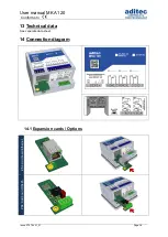
a ZS4 board
(expansion card RS485, see Figure 14:
12.2 Enabling VisuNet-Program
– Code 8305 (VisuNet)
In order to work with the visualisation program is has to be enabled. You will need an appliance
specific PIN which you will receive from aditec.
There are 2 options for enabling the visualisation program:
1.
BASE version:
enables
the basic functions of the visualisation program are enabled, as well
as the profile recording feature and the logging of measured data.
2.
COMFORT version:
enables the extended option of the visualisation program which includes
the option of configuring and changing programs, additional recording feature
(e.g. the status
of the relays and the digital inputs)
etc.
Hint
Enabling the COMFORT version
I
f a controller has been enabled as „COMFORT“ version, it will be automatically recognised
as such by VisuNet, therefore it does not need to be specifically enabled for VisuNet.
A BASE version can always be converted into a COMFORT version.
Be aware
If you enter a wrong PIN, the message
„wrong PIN“ will be shown together with the remaining
number of attempts to enter a correct PIN.
If you have entered the PIN number incorrectly 3 times in a row, you can still enable VisuNet
with a PUK number. If both numbers have been entered incorrectly 3 times in a row, the
controller will have to be sent back to aditec.
Hint
You will receive a separate user manual for VisuNet with instructions on how to install and
operate it.
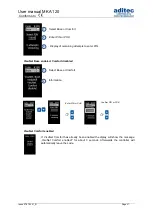
Factory setting: VisuNet is not enabled
VisuNet
Profiles
3 Sec.
Figure 14:
ZS4 board

