background image

Chapter 3: Connectors and Indicators

Connector or Indicator

Description

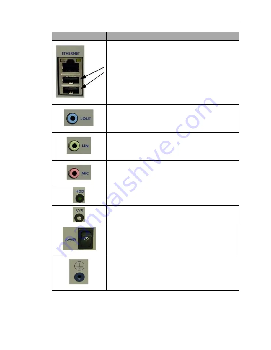
Use the USB connectors for a USB keyboard and mouse.

This is only used for an upgrade.

Use the blue line-out connector to attach headphones and most speakers
with integrated amplifiers.
This connector, while functional, currently has no application to Adept
systems.

Use the green line-in connector to attach a record/playback device such
as a CD-ROM.
This connector, while functional, currently has no application to Adept
systems.

Use the pink connector to attach a personal computer microphone.
This connector, while functional, currently has no application to Adept
systems.

The HDD indicator monitors the hard drive. The indicator light is illu-
minated when the hard drive is being accessed.

The System Power (SYS) is illuminated whenever the Adept SmartFleet
EX is powered on.

The power switch is a toggle switch. Press the switch once to enable
power. Pressing this switch while the power is on powers off the Adept
SmartFleet EX.
By default, the Adept SmartFleet EX automatically powers on when 24
volts is applied.

This ground point is not used.
This is not the same as the chassis ground, which is located on the left
side of the Adept SmartFleet EX.

Adept SmartFleet EX User’s Guide, Rev. A

Page 23 of 54

Summary of Contents for SmartFleet EX

Page 1: ...Adept SmartFleet EX Appliance User s Guide Including the Enterprise Manager and Fleet Manager...

Page 2: ......

Page 3: ...11445 000 Rev A March 2012 5960 Inglewood Drive Pleasanton CA 94588 USA Phone 925 245 3400 Fax 925 960 0452 Otto Hahn Strasse 23 44227 Dortmund Germany Phone 49 231 75 89 40 Fax 49 231 75 89 450 Block...

Page 4: ...welcomed Your comments assist us in preparation of future documentation Please submit your comments to techpubs adept com Copyright 2012 by Adept Technology Inc Adept the Adept logo the Adept Technolo...

Page 5: ...lated Manuals 14 Adept Document Library 14 Chapter 2 Installation 15 2 1 Site Preparation 15 2 2 Transport and Storage 15 2 3 Before Unpacking 15 Inspecting 16 2 4 Mounting the Adept SmartFleet EX 16...

Page 6: ...dept SmartFleet EX Appliance 33 Enabling Enterprise Manager 33 4 12 Customizing Each Robot 34 Separate Charging Stations MT400 Robots 34 Distinct Voices 34 Chapter 5 Operation 35 5 1 Turning Power ON...

Page 7: ...Specifications 49 7 1 Processing Specifications 49 7 2 Environmental Specifications 49 7 3 Power Requirements 49 7 4 Dimensions 50 7 5 Connections 51 External 51 Internal 51 Optional 51 Adept SmartFle...

Page 8: ......

Page 9: ...sks Adept Fleet Manager The Adept Fleet Manager allows you to manage map and configuration updates in a central location These are then pushed out to each robot in the fleet It also allows the mobile...

Page 10: ...dept Fleet Manager software Both applications running on the Adept SmartFleet EX appliance l Allow you to manage the configuration for the entire fleet of robots Each robot downloads its configuration...

Page 11: ...ower outages without a loss it is solely dedicated to the task and won t be affected by other services and if something happens to the appliance it can be replaced and the new one will operate identic...

Page 12: ...In descending order of importance they are DANGER This indicates an imminently hazardous electrical situation which if not avoided will result in death or serious injury DANGER This indicates an immi...

Page 13: ...drop down list select Manufacturer Declarations 2 From the Product drop down list select the product category 3 Click Begin Search The list of available documents is shown in the Search Results area...

Page 14: ...y aspect for Adept robots Adept Motivity User s Guide Describes the software for mobile robots Enterprise Manager and Fleet Manager Adept MT400 Robot User s Guide Describes the operation and maintenan...

Page 15: ...be allowed for the manufacturing management system to initiate a con nection with the Adept Enterprise Manager or Adept Fleet Manager Static IP addresses are needed for the Adept SmartFleet EX applia...

Page 16: ...et EX appliance is not intended for use in hazardous environments explo sive gas water dust oil mist It has an IP rating of IP 20 NEMA Type 1 Space Around the Chassis When the appliance is installed y...

Page 17: ...22 2 TYP 4x 462 482 8 R3 6 TYP THRU 3 6 TYP 2x 77 2x 09228 100 1 3 6 REMOVABLE FEET 18 5 29 14 2 1 5 2x M3 x 6MM BOTH SIDES 188 8 Figure 2 1 Rack Mounting the Adept SmartFleet EX Adept SmartFleet EX...

Page 18: ...2x 120 9 16 TYP 2x 21 6 2x 16 3 4x M3 x 6mm BOTH SIDES Figure 2 3 Figure 2 2 Table Mounting the Adept SmartFleet EX 2 5 Connecting Power The Adept SmartFleet EX comes with an in line 24 VDC power supp...

Page 19: ...cting a ground wire from the chassis ground point on the Adept SmartFleet EX to earth ground The ground wire must meet all local regulations NOTE This is not the same as the 24 VDC ground on the front...

Page 20: ......

Page 21: ...ctor attached In less common cases one or both expansion slots will have GigE cards that may be connected during normal use l The Maint Eth port is only used during setup l The connectors for mouse ke...

Page 22: ...on a monitor See Connecting a Monitor on page 25 This is only used for an upgrade Use an Ethernet connector for connecting the Adept SmartFleet EX to a network See Connecting to a Network on page 25...

Page 23: ...personal computer microphone This connector while functional currently has no application to Adept systems The HDD indicator monitors the hard drive The indicator light is illu minated when the hard d...

Page 24: ...rd and mouse will only be needed for major OS upgrades in the field and are not commonly used The PS 2 connectors shown in the following figure allow you to use a PC compatible keyboard and mouse with...

Page 25: ...ON Do not connect the Adept SmartFleet EX appliance to the internet Adept recommends that you use Category 5 or better wiring and connectors for your network If you must use Category 3 wiring limit th...

Page 26: ...Power Power Switch The front panel power switch turns on or off 24 V power to the Adept SmartFleet EX Pressing this switch while the power is on powers off the Adept SmartFleet EX 24 VDC Connector The...

Page 27: ...igure the Adept SmartFleet EX use the LAN port to connect the unit to your network l an Ethernet port This port is used to connect the unit to your LAN NOTE Contact your System Administrator for assis...

Page 28: ...the Maintenance Ethernet port which does not require a password and has a fixed IP address 1 2 3 4 4 5 Connecting to SetNetGo SetNetGo lets you manage a variety of settings update the robot s systems...

Page 29: ...artFleet EX in the IP Address field Do not use the IP address 1 2 3 4 because this would create a conflict with the IP address permanently set for the Maintenance Ethernet port 4 Enter the appropriate...

Page 30: ...e SetNetGo password field 2 Re enter the password in the Confirm Password field 3 Click Apply Synchronizing Time The robots clocks can be synchronized with either the Adept SmartFleet EX clock or with...

Page 31: ...box and then clicking Apply If any robot in your fleet will be using lead acid batteries you need to enable that feature on the appliance This is done in the Custom arguments field which is just belo...

Page 32: ...he configuration tasks described above you can physically connect the Adept SmartFleet EX to your network 1 Start up a web browser on a PC connected to your network 2 Enter https X X X X in the addres...

Page 33: ...leCentralServerGatherScans box This lets the Adept Enterprise Manager or Adept Fleet Manager gather any scan files created by the robots 4 It s also a good idea to check EnableDeleteUnusedMaps This de...

Page 34: ...at the end of the Available ARAM Features sec tion 1 In the Custom arguments field add separateSection Docking The separateSection restricts the effect of this parameter to just this robot 2 Click App...

Page 35: ...BIOS In rare cases this feature may get disabled by a CMOS battery failure 5 2 Updating ARAM If you have a valid aramcentral tgz file you can update the ARAM version on the Adept Smart Fleet EX appli...

Page 36: ...iguration default settings from Set NetGo l Original Account Settings l Originally enabled ARAM features To restore network and general settings 1 Connect to SetNetGo see Connecting to SetNetGo for de...

Page 37: ...t for a pickup PICKUP for which the delivery des tination DROPOFF is not yet known queuePickup ARCL command It is assumed that the delivery destination will be communicated directly to the robot that...

Page 38: ...essed l Completed jobs that were successfully processed l Failed jobs that failed due to reasons such as a blocked path or E Stop These jobs will not be retried l Canceled jobs that were manually canc...

Page 39: ...mple usage scenarios and require some application layer support to fully implement The following flowchart illustrates a simple pickup and delivery cycle Other factors such as state of charge can alte...

Page 40: ...ration Queuing Manager The parameters that control the way that the Adept Enterprise Manager handles queueing are l IdleTimeUntilResume Number of minutes to wait after a robot becomes available before...

Page 41: ...rge when it completes a job it will be sent to dock The robot will continue completing its assigned jobs until it reaches the SOC settings in Docking AutoDockStateOfCharge NOTE A robot will drive to i...

Page 42: ...Maximum number of completed jobs to keep The following screen shows configuration parameters that need to be set for queueing Figure 5 3 Queueing Parameters The following screen shot shows the comman...

Page 43: ...bileEyes at 1 2 3 4 ARAM configuration error Verify ARAM is installed and running Check ARAM Logs in SetNetGo Verify ARAM startup arguments Can t ping LAN address at Ethernet interface LAN configurati...

Page 44: ...File The debug file can be retrieved by opening a web browser and entering the URL https your_EnterpriseManager_IP such as If the Adept SmartFleet EX has not been setup on the main LAN then a direct c...

Page 45: ...ort of your computer to robot s maintenance port Maint Eth Open a web browser and enter the URL https 1 2 3 4 In either case you will be requested to confirm security certificates You should now have...

Page 46: ...ft pane and select Debug Info circled in red in the pre vious figure This will display a Download debug info button 2 Select Download debug info 3 Save the file and attach it to your support request A...

Page 47: ...two expansion slots which support the following PCIe card option l GigE card 1 port per card 6 3 Installing PCIe Cards This section gives instructions for installing a PCIe card 1 Unplug the external...

Page 48: ...ysically clicks into place 6 Attach the PCIe card to the frame with one of the thumbscrews See the preceding figure 7 After installing PCIe card s reconnect the internal 24 V plug 8 Cable tie any unus...

Page 49: ...pt SmartFleet EX must be shipped and stored in a temperature controlled envi ronment Refer to the following table Table 7 2 Environmental Specifications Ambient temperature 5 to 40 C 41 to 104 F Stora...

Page 50: ...ht of the Adept SmartFleet EX Table 7 4 Physical Specifications Weight 2 69 kg 5 92 lbs Dimensions Width 328 9 mm 12 9 in Depth 185 4 mm 7 3 in Height 63 6 mm 2 5 in box only 69 4 mm 2 73 in with feet...

Page 51: ...USB 2 0 x 4 l RS 232 DB9M x 2 not used l VGA HDB15F l DVI l PS 2 Mouse l PS 2 Keyboard l Audio In not used l Audio Out not used l Microphone Jack not used Internal l PCIe card slots x 2 Optional Optio...

Page 52: ......

Page 53: ......

Page 54: ...P N 11445 000 Rev A 5960 Inglewood Drive Pleasanton CA 94588 925 245 3400...

Reviews: