


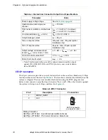

Installing Robot Solenoid Kit
Adept Cobra s800 Inverted Robot User’s Guide, Rev C
79
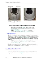
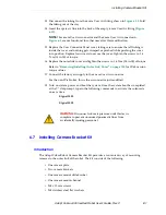
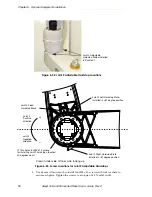
2. Remove three screws on each side of the outer link cover. Remove two screws on
top and remove the cover.
For the IP-65 version, refer to
“Removing/Installing Outer Link Cover” on page
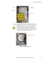
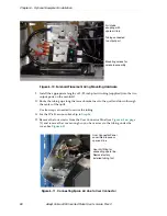
3. Connect the Internal Solenoid Valve Cable assembly to the Solenoid Manifold
assembly, by plugging the SOL 1 connector into Valve 1 and SOL 2 into Valve 2.
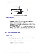
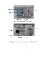
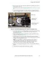
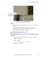
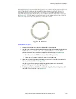
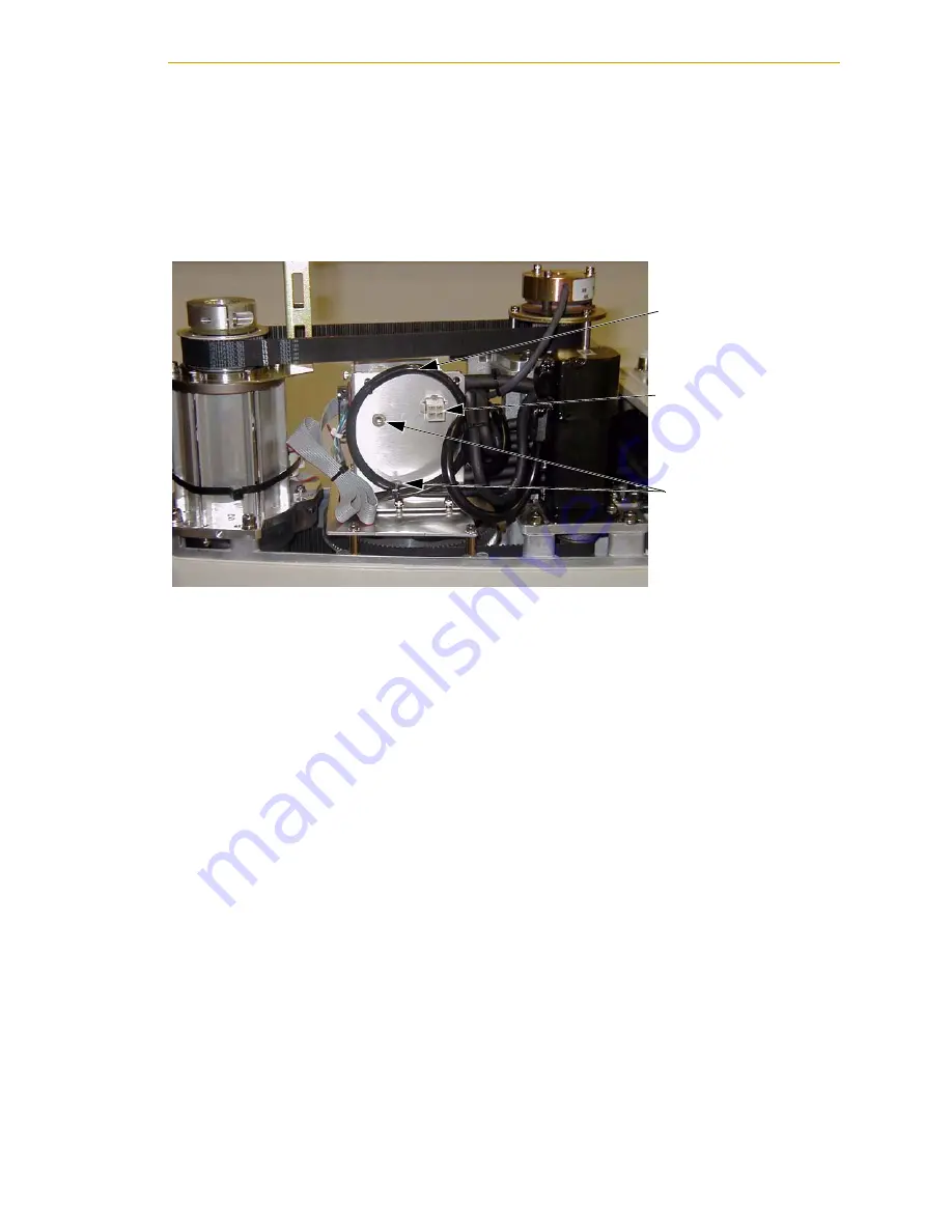
Figure 6-9. Solenoid Mounting Bracket with Connector and Spare Air Line
4. Cut and discard the tie-wraps holding the spare air line at the top of the mounting
bracket. Move the air line away to facilitate the mounting of the solenoid
manifold (see
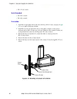
5. Mount the solenoid manifold onto the bracket using the supplied M3 x
30
mm
screws and washers (see
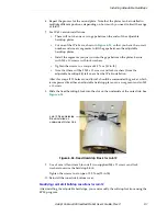
6. Insert the spare air line into the air intake coupling of the solenoid manifold.
Make sure the air line is pushed in all the way and secured in place by the intake
coupling. Confirm by pulling the air line.
NOTE:
If you are installing on an IP-65 robot, the spare air line is used for
a different purpose in those robots. You will have to provide a piece of 6
mm tubing to run from one of the 6 mm user airlines at the Joint 2 cover
(under the cover for the IP-65 version) to the air intake coupling.
7. Plug the connector plug into the female connector jack (marked SOLND) on the
bracket.
8. Use tie-wraps to secure the air line to the bracket as needed.
Pem nuts to mount the
solenoid manifold
Connector for the
solenoid valves
Spare air line